3
Setting Up | A | |
Your Snow | ||
| ||
Thrower | B |
NOTE: References to |
|
right or left side of the | Figure |
snow thrower are deter- |
|
mined from behind the |
|
unit in the operating |
|
position. |
|
NOTE: This Operator’s |
|
Manual covers several |
|
models, handle panels, |
|
lights and chute cranks |
|
are some features that |
|
may vary by model. |
|
Not all features refer- |
|
enced in this manual |
|
are applicable to all |
|
snow thrower models. | Figure |
NOTE: Two replace- ment auger shear pins are included with this manual (or stowed
in the plastic handle panel). Refer to Augers in the Maintainance Section for more information regarding shear pin replacement.
Figure
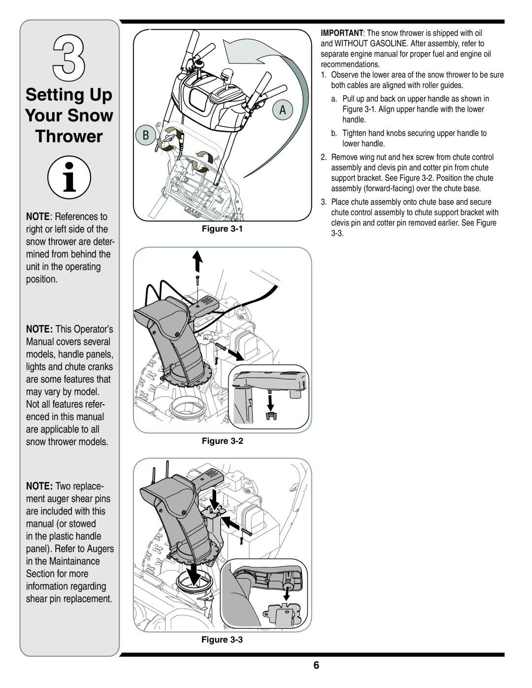
IMPORTANT: The snow thrower is shipped with oil and WITHOUT GASOLINE. After assembly, refer to separate engine manual for proper fuel and engine oil recommendations.
1.Observe the lower area of the snow thrower to be sure both cables are aligned with roller guides.
a.Pull up and back on upper handle as shown in Figure
b.Tighten hand knobs securing upper handle to lower handle.
2.Remove wing nut and hex screw from chute control assembly and clevis pin and cotter pin from chute support bracket. See Figure
3.Place chute assembly onto chute base and secure chute control assembly to chute support bracket with clevis pin and cotter pin removed earlier. See Figure