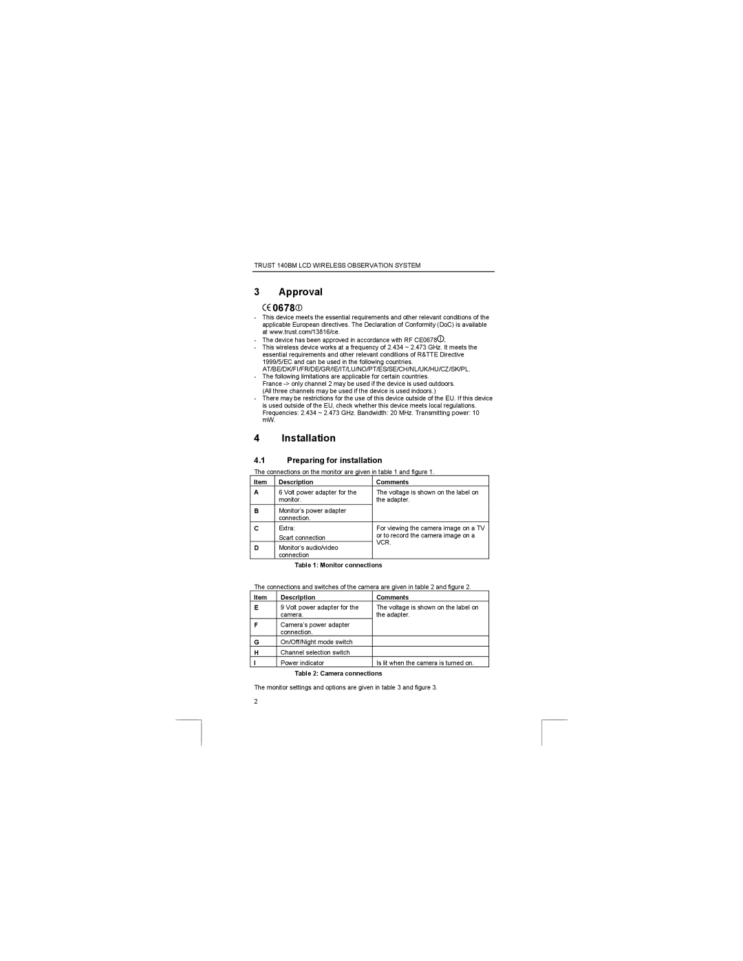
140BM specifications
The Trust Computer Products 140BM model is a versatile and innovative solution that caters to the diverse needs of modern users in both home and office environments. This device has been developed with an emphasis on enhanced performance, reliability, and user-friendliness, making it a popular choice for various applications.One of the standout features of the 140BM is its robust processing power. Equipped with a state-of-the-art processor, this model ensures swift execution of tasks while maintaining energy efficiency. Users can expect seamless multitasking capabilities, which are particularly beneficial for those who run multiple applications simultaneously or engage in resource-intensive processes.
The 140BM boasts a high-resolution display, providing sharp and vivid visuals. Whether for professional presentations, graphic design work, or simply enjoying multimedia content, the screen delivers exceptional clarity and color accuracy. Additionally, its adjustable brightness settings allow for comfortable viewing in various lighting conditions, enhancing the overall user experience.
Connectivity is another crucial aspect of the 140BM. The device features multiple USB ports, an HDMI output, and an Ethernet port, enabling easy connections to various peripherals and networks. Wireless connectivity options, including Wi-Fi and Bluetooth, further enhance its compatibility with external devices, allowing users to connect seamlessly to printers, headphones, and other smart devices.
In terms of storage, the 140BM incorporates advanced solid-state drive (SSD) technology. This not only maximizes data transfer speeds, significantly reducing boot and load times, but also enhances the overall system performance. The spacious storage capacity provides ample room for files, applications, and multimedia content, making it suitable for both personal and professional use.
The design of the 140BM emphasizes ergonomics and aesthetics. With a sleek and modern exterior, it fits well into any workspace. The device is also lightweight and portable, making it ideal for users who need to travel frequently or move between different locations.
In conclusion, the Trust Computer Products 140BM is a powerful, efficient, and stylish device that adapts to the myriad needs of today’s users. Its high-performance specifications, advanced connectivity options, and user-friendly design make it a reliable choice for anyone looking to enhance their productivity and digital experience. Whether used for work, study, or leisure, the 140BM delivers outstanding performance and versatility.

