![]() CAUTION
CAUTION
DO NOT use any type of cleaner on the condenser unit.
4.Clean the condenser coil (Figure 11, 2) using a soft brush with a “combing” action or vacuum cleaner. Do not touch the condenser coil.
5.Position the grille to align the mounting screws with the holes in the cabinet.
6.Secure, but do not
7.Reconnect power to the unit.
Ice Maker Maintenance
Inlet Screen
Interval - Every Twelve Months
The solenoid valve inlet screen must be cleaned at least once each year as follows:
1.Shut off the water at the main supply valve.
2.Pull the unit out to access the back panel.
3.Disconnect electrical power to the unit.
2
1
ULIN_0054_A
Figure 12
4.Disconnect the hose connector (Figure 12, 1) from the water solenoid valve (Figure 12, 2).
5.DO NOT remove the inlet screen from the water solenoid valve. Use a tooth brush to gently clean any sediment from the inlet screen.
6.
7.Open the water main supply valve and check for leakage at the water hose connection. Ensure that the water supply line is not kinked.
8.Reconnect power to the unit before
Ice Cube Thickness Adjustment
Interval - As Required
On ice maker equipped models, the cube size may be adjusted by changing the amount of water injected into the ice maker assembly as follows:
ULIN_0259_A
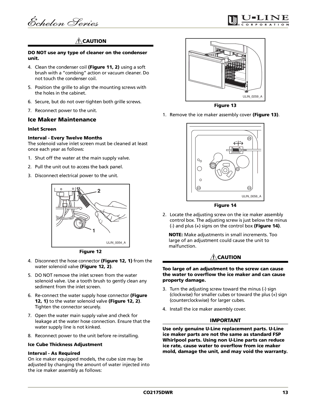
Figure 13
1. Remove the ice maker assembly cover (Figure 13).
ULIN_0056_A |
Figure 14
2.Locate the adjusting screw on the ice maker assembly control box. The adjusting screw is just below the minus
NOTE: Make adjustments in small increments. Too large of an adjustment could cause the unit to malfunction.
![]() CAUTION
CAUTION
Too large of an adjustment to the screw can cause the water to overflow the ice maker and can cause property damage.
3.Turn the adjusting screw toward the minus
4.Install the ice maker assembly cover.
IMPORTANT
Use only genuine
CO2175DWR | 13 |