2.Determine the number and configuration of Lamp Modules and Power Junction Modules. Note: the maximum number of Lamp Modules
3.Mark the location of the lower mounting bracket on the lower mounting surface of the installation area.
4.Measure overall length/height required for the installation (Figure 2a, dimension ‘A’). This dimension is the distance from the lower mounting surface to the upper mounting surface of the mounting location. Record the measurement in the table in Figure 2a. for Dimension A.
5.Referencing Dimension A, deduct ½” from the overall distance from the lower to upper mounting surface and record as Dimension B. This is the overall length of the Main Support.
6.Install the lower bracket to the lower mounting surface of the installation area in the previously marked location. Four sheet metal screws (provided) should be used to securely fasten the lower bracket to the lower mounting surface (see Figure 2a).
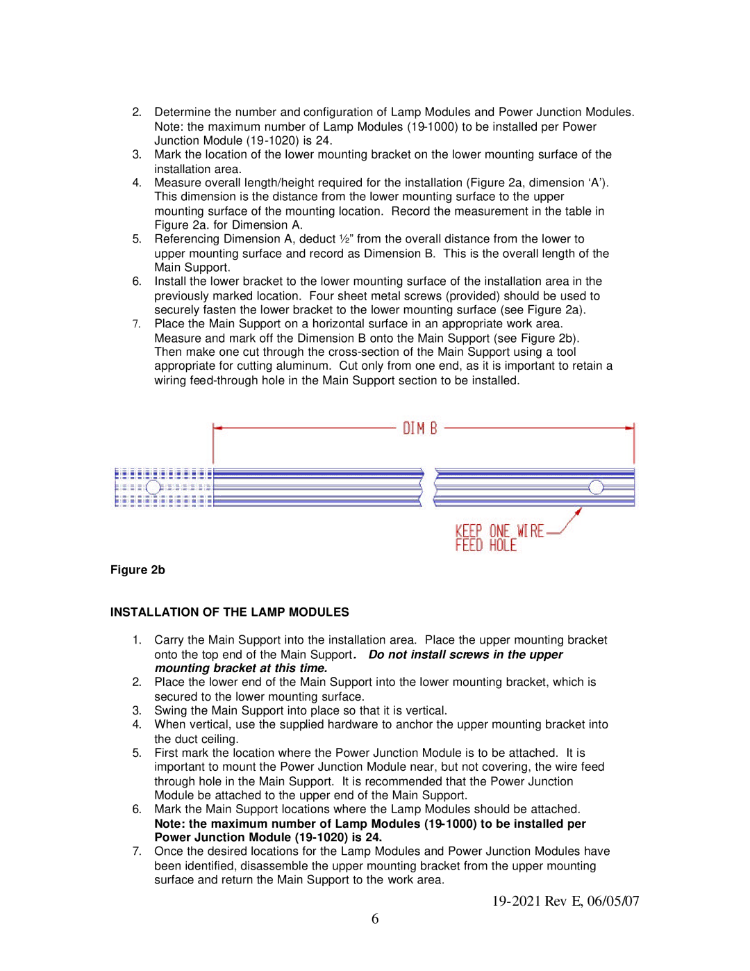
7.Place the Main Support on a horizontal surface in an appropriate work area. Measure and mark off the Dimension B onto the Main Support (see Figure 2b). Then make one cut through the
Figure 2b
INSTALLATION OF THE LAMP MODULES
1.Carry the Main Support into the installation area. Place the upper mounting bracket onto the top end of the Main Support. Do not install screws in the upper mounting bracket at this time.
2.Place the lower end of the Main Support into the lower mounting bracket, which is secured to the lower mounting surface.
3.Swing the Main Support into place so that it is vertical.
4.When vertical, use the supplied hardware to anchor the upper mounting bracket into the duct ceiling.
5.First mark the location where the Power Junction Module is to be attached. It is important to mount the Power Junction Module near, but not covering, the wire feed through hole in the Main Support. It is recommended that the Power Junction Module be attached to the upper end of the Main Support.
6.Mark the Main Support locations where the Lamp Modules should be attached.
Note: the maximum number of Lamp Modules
7.Once the desired locations for the Lamp Modules and Power Junction Modules have been identified, disassemble the upper mounting bracket from the upper mounting surface and return the Main Support to the work area.
6