8.Select one side of the Main Support to start assembly of lamp modules. Begin assembly of the Lamp Modules attachments first (see Figure 3b). Begin by installing the Lamp Module furthest from the Power Junction Module location.
9.Thread the three wires from the last Lamp Module installed to the main extrusion through the strain relief and into the wiring compartment of the next Lamp Module.
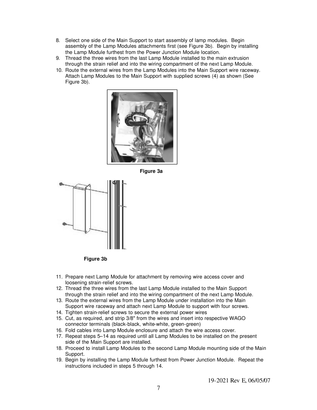
10.Route the external wires from the Lamp Modules into the Main Support wire raceway. Attach Lamp Modules to the Main Support with supplied screws (4) as shown (See Figure 3b).
Figure 3a
Figure 3b
11.Prepare next Lamp Module for attachment by removing wire access cover and loosening
12.Thread the three wires from the last Lamp Module installed to the Main Support through the strain relief and into the wiring compartment of the next Lamp Module.
13.Route the external wires from the Lamp Module under installation into the Main Support wire raceway and attach next Lamp Module to support with four screws.
14.Tighten
15.Cut, as required, and strip 3/8" from the wires and insert into respective WAGO connector terminals
16.Fold cables into Lamp Module enclosure and attach the wire access cover.
17.Repeat steps
18.Proceed to install Lamp Modules to the second Lamp Module mounting side of the Main Support.
19.Begin by installing the Lamp Module furthest from Power Junction Module. Repeat the instructions included in steps 5 through 14.
19-2021 Rev E, 06/05/07
7