Assembly of Furnace
Your furnace requires the following items to be assembled or installed by the service person:
BLOWER AND BLOWER CONTROLS
ELECTRICAL CONNECTIONS
1. Remove all parts from inside the furnace and inspect for damage. Including the firebrick, as some damage could have occurred during shipment.
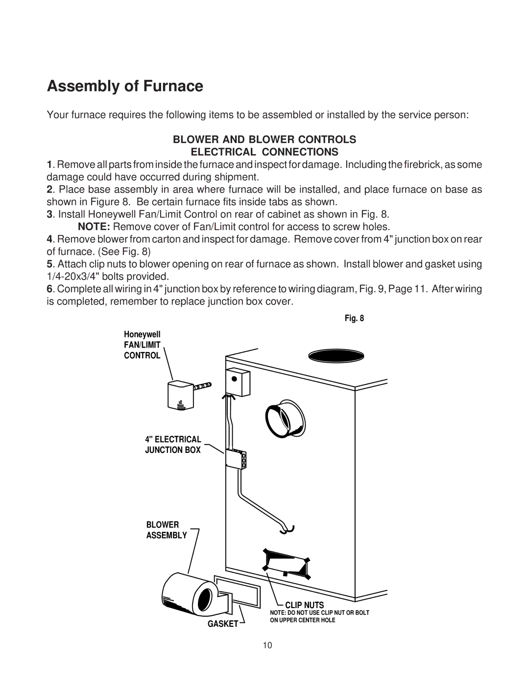
2. Place base assembly in area where furnace will be installed, and place furnace on base as shown in Figure 8. Be certain furnace fits inside tabs as shown.
3. Install Honeywell Fan/Limit Control on rear of cabinet as shown in Fig. 8. NOTE: Remove cover of Fan/Limit control for access to screw holes.
4. Remove blower from carton and inspect for damage. Remove cover from 4" junction box on rear of furnace. (See Fig. 8)
5. Attach clip nuts to blower opening on rear of furnace as shown. Install blower and gasket using
6. Complete all wiring in 4" junction box by reference to wiring diagram, Fig. 9, Page 11. After wiring is completed, remember to replace junction box cover.
Fig. 8
Honeywell
FAN/LIMIT
CONTROL
4" ELECTRICAL JUNCTION BOX
BLOWER
ASSEMBLY
CLIP NUTS
GASKET
NOTE: DO NOT USE CLIP NUT OR BOLT ON UPPER CENTER HOLE
10