
1602M specifications
The United States Stove 1602M is a highly regarded model in the world of wood and coal stoves, designed to provide efficient heating with a classic aesthetic that complements any home décor. This model is particularly popular among eco-conscious homeowners seeking to reduce their carbon footprint. The stove's robust construction and advanced features make it an excellent choice for those who desire both functionality and reliability.One of the main features of the United States Stove 1602M is its impressive heating capacity. With a heating area suitable for up to 1,200 square feet, it is perfect for small to medium-sized rooms. The stove’s nominal output of 70,000 BTUs ensures that it can effectively warm up spaces on even the coldest days, providing a cozy environment for the household.
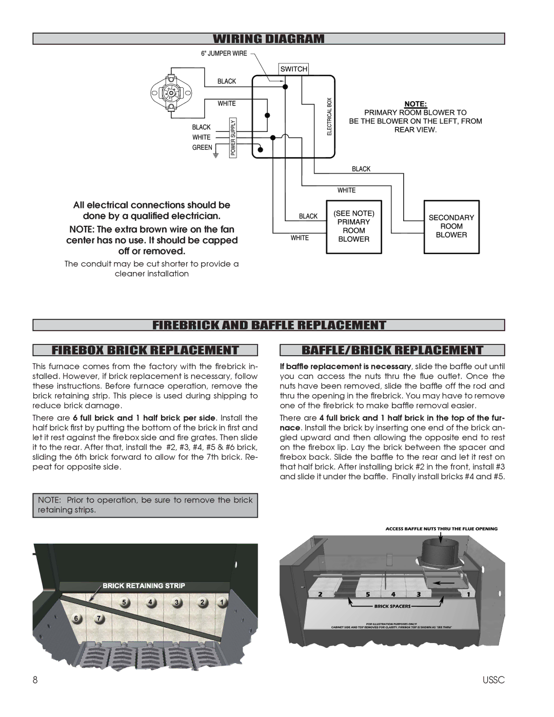
The 1602M employs a traditional front-loading design, which makes fueling the stove straightforward and convenient. It is built with a firebrick-lined interior, which enhances heat retention and promotes efficient combustion. This design feature allows the stove to radiate heat evenly while maximizing the burn time of the fuel used.
One of the standout technologies integrated into this stove is its advanced air wash system, designed to keep the glass door clean and free from soot buildup. This feature allows for an unobstructed view of the flickering flames, enhancing the ambiance of the home. The stove is equipped with an adjustable primary air control, which grants users the ability to regulate the airflow according to their heating needs.
Built with durable cast iron materials, the 1602M is designed to withstand high temperatures while maintaining its structural integrity over time. The classic matte black finish adds to the stove's aesthetic appeal, ensuring it fits seamlessly into various interior styles, from rustic to contemporary.
Safety is also a priority with the United States Stove 1602M. It comes with a built-in safety screen and a thermal safety shut-off feature that prevents overheating. This aspect enhances peace of mind for users, especially in households with children or pets.
In summary, the United States Stove 1602M is a blend of tradition and modern technology, offering efficient heating performance, user-friendly operation, and safety features that make it an outstanding choice for warmth and comfort during the colder months. Its combination of form and function makes it a worthwhile investment for any home.