Masonry, or other
A variety or prefabricated clearance reduction systems which have been tested and listed are available through heater dealers. Always look for a safety listing label on the product when selecting a clearance reduction system and make sure it is designed for solid fuel appliances. The manufactures of these systems provide specific installation instructions that must be followed exactly for a safe installation.
Should you choose to make your own clearance reduction system, contact your local fire department, fire marshal or building code inspector for specific requirements regarding home constructed clearance reduction systems and safe installation clearances to protect combustible materials.
CAUTION: READ ALL INSTRUCTIONS BEFORE INSTALLING THE HEATER.
TO INSTALL THE HEATER:
1.Make ready a suitable chimney. The chimney must complywith the requirements for Type
2.Gather the necessary materials, tools, and supplies which will be needed to install the heater.
CAUTION: DO NOT USE MORE THAN ONE 90 DEGREE BEND (ELBOW) IN THE CHIMNEY CONNECTOR INSTALLATION. MORE THAN ONE 90 DEGREE BEND (ELBOW) IN THE CHIMNEY CONNECTOR COULD NEGA- TIVELY AFFECT CHIMNEY DRAFT.
3.I f the floor on which the heater is to be installed is wood or any other combustible material, place a floor protector (described earlier) on the floor where the heater will be installed.
CAUTION: THE FLOOR PROTECTOR MUST NOT BE PLACED ON CARPET. REMOVE CARPET FROM BENEATH THE FLOOR PROTECTOR.
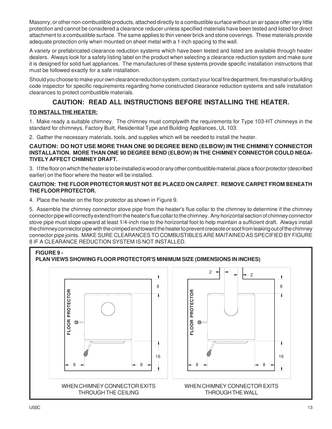
4.Place the heater on the floor protector as shown in Figure 9.
5.Assemble the chimney connector stove pipe from the heater's flue collar to the chimney to determine if the chimney connector pipe will correctly extend from the heater's flue collar to the chimney. Any horizontal section of chimney connector stove pipe must slope upward at least
8IF A CLEARANCE REDUCTION SYSTEM IS NOT INSTALLED.
FIGURE 9 - |
|
|
|
|
PLAN VIEWS SHOWING FLOOR PROTECTOR'S MINIMUM SIZE (DIMENSIONS IN INCHES) |
| |||
|
| 2 | 2 |
|
|
|
|
| |
FLOOR PROTECTOR | 8 | FLOOR PROTECTOR |
| 8 |
|
|
| ||
| 16 |
|
| 16 |
8 | 8 | 8 |
| 8 |
WHEN CHIMNEY CONNECTOR EXITS | WHEN CHIMNEY CONNECTOR EXITS | |||
| THROUGH THE CEILING | THROUGH THE WALL |
| |
USSC |
|
|
| 13 |