Issue 1
INSTALLATION INSTRUCTIONS
INTRODUCTION
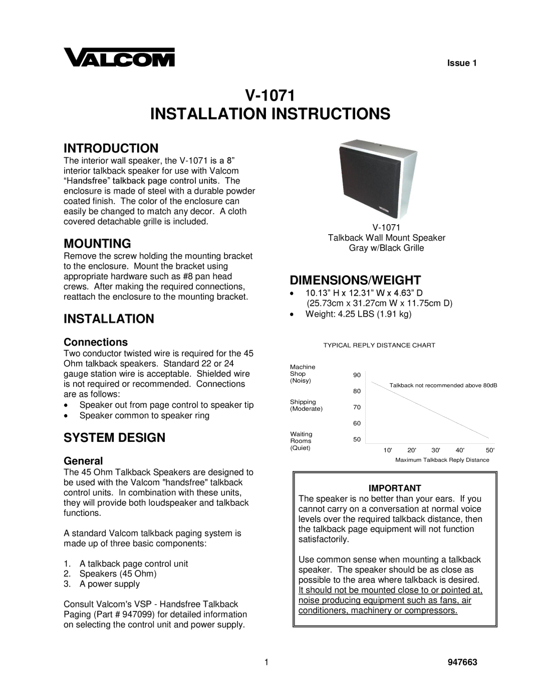
The interior wall speaker, the
MOUNTING
Remove the screw holding the mounting bracket to the enclosure. Mount the bracket using appropriate hardware such as #8 pan head crews. After making the required connections, reattach the enclosure to the mounting bracket.
INSTALLATION
Connections
Talkback Wall Mount Speaker
Gray w/Black Grille
DIMENSIONS/WEIGHT
10.13” H x 12.31” W x 4.63” D (25.73cm x 31.27cm W x 11.75cm D) Weight: 4.25 LBS (1.91 kg)
TYPICAL REPLY DISTANCE CHART
Two conductor twisted wire is required for the 45 Ohm talkback speakers. Standard 22 or 24 gauge station wire is acceptable. Shielded wire is not required or recommended. Connections are as follows:
Speaker out from page control to speaker tip Speaker common to speaker ring
SYSTEM DESIGN
General
Machine
Shop90 (Noisy)
80
Shipping
(Moderate)70
60
Waiting
Rooms50 (Quiet)
Talkback not recommended above 80dB
10' | 20' | 30' | 40' | 50' |
Maximum Talkback Reply Distance
The 45 Ohm Talkback Speakers are designed to be used with the Valcom "handsfree" talkback control units. In combination with these units, they will provide both loudspeaker and talkback functions.
A standard Valcom talkback paging system is made up of three basic components:
1.A talkback page control unit
2.Speakers (45 Ohm)
3.A power supply
Consult Valcom's VSP - Handsfree Talkback Paging (Part # 947099) for detailed information on selecting the control unit and power supply.
IMPORTANT
The speaker is no better than your ears. If you cannot carry on a conversation at normal voice levels over the required talkback distance, then the talkback page equipment will not function satisfactorily.
Use common sense when mounting a talkback speaker. The speaker should be as close as possible to the area where talkback is desired. It should not be mounted close to or pointed at, noise producing equipment such as fans, air conditioners, machinery or compressors.
1 | 947663 |
