1A2 TELEPHONES | PUNCHDOWN |
|
|
|
| |||||
BLOCK |
|
|
| |||||||
PAGE BUTTON |
|
|
| |||||||
|
|
|
|
|
|
|
|
|
|
|
TIP |
| (W/BL) | 26 |
|
|
| T | (W/BL) | ||
RING |
| (BL/W) | 1 |
|
|
| R | (BL/W) | ||
LAMP |
|
|
|
|
| H | (W/O) |
| ||
|
|
|
|
| ||||||
LGND |
|
|
|
|
|
| ||||
|
|
|
|
| DIR |
| ||||
|
|
|
|
|
|
| ||||
|
|
|
|
|
| (W/G) |
|
|
| |
|
|
|
|
|
|
| ||||
BFT (W/S)
BFR (S/W)
|
| A1 | (R/BL) |
|
|
|
| A1 | (BL/R) |
|
|
POWER SUPPLY | (R/O) | 32 |
| A2 | (R/O) |
|
| A2 | (O/R) | ||
| (O/R) | 7 |
| ||
|
| MT | (R/G) | ||
LAMP GROUND |
| PG (R/BR) | |||
| MR | (G/R) | |||
| OUT (BR/R) | ||||
LAMP BATTERY |
| ||||
|
|
| |||
(V/BR) | 49 |
| AG (V/BR) | ||
A GROUND |
| ||||
(BR/V) | 24 |
| AB (BR/V) | ||
A BATTERY |
| ||||
(V/S) | 50 |
| BG (V/S) | ||
B GROUND |
| ||||
(S/V) | 25 |
| BB (S/V) | ||
B BATTERY |
| ||||
|
|
|
|
| |
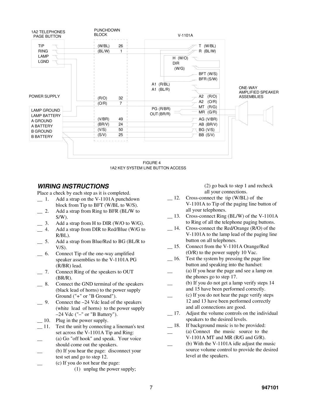
FIGURE 4
1A2 KEY SYSTEM LINE BUTTON ACCESS
WIRING INSTRUCTIONS
Place a check by each step as it is completed.
__ 1. | Add a strap on the | |
|
| block from Tip to BFT (W/BL to W/S). |
__ 2. | Add a strap from Ring to BFR (BL/W to | |
|
| S/W). |
__ 3. | Add a strap from H to DIR (W/O to W/G). | |
__ 4. | Add a strap from DIR to Red/Blue (W/G to | |
|
| R/BL). |
__ 5. | Add a strap from Blue/Red to BG (BL/R to | |
|
| V/S). |
__ | 6. | Connect Tip of the |
|
| speaker assemblies to the |
|
| (R/BR) lead. |
__ 7. | Connect Ring of the speakers to OUT | |
|
| (BR/R). |
__ | 8. | Connect the GND terminal of the speakers |
|
| (black lead of horns) to the power supply |
|
| Ground ("+" or "B Ground"). |
__ | 9. | Connect the |
|
| (white lead of horns) to the power supply |
|
| |
__ 10. | Plug in the power supply. | |
__ 11. | Test the unit by connecting a lineman's test | |
|
| set across the |
__ |
| (a) Go "off hook" and speak. Your voice |
|
| should come out the speakers. |
__ |
| (b) If you hear the page: disconnect your |
|
| test set and go to step 12. |
__ |
| (c) If you do not hear the page: |
|
| (1) unplug the power supply; |
(2) go back to step 1 and recheck all your connections.
__ 12.
__ 13.
__ 14.
| button on all telephones. |
__ 15. Connect from the | |
| (O/R) to the power supply 10 Vac. |
__ 16. Test the system by pressing the page line | |
| button and speaking into the handset: |
__ | (a) If you hear the page and see a lamp on |
| the phones go to step 17. |
__ | (b) If you do not get a lamp verify steps 14 |
| and 15 have been performed correctly. |
__ | (c) If you do not hear the page verify steps |
| 12 and 13 have been performed correctly |
| and all connections are good. |
__ 17. | Adjust the volume controls on the individual |
| speakers to the desired levels. |
__ 18. | If background music is to be provided: |
__ | (a) Connect the music source to the |
| |
__ | (b) With the |
| source volume control to provide the desired |
| level at the speakers. |
7 | 947101 |