INSTALLATION

Installing Blower Accessory - GA3450T(Cont.)

13

INSTALLATION

Continued

9.Install the switch plate on the valve cover shield with 2 #10 screws provided (see Figure 18, page 12). Reinstall the valve cover shield. Route power cord out of the cabinet by inserting it through the bushing on the outer casing (see Figure 18, page 12). Plug fan kit into 120-Volt grounded power supply and test operation. Note: When switch is in the AUTO position, the fan will start after the heater has run for a few moments. The fan will continue to run for several moments after the heater has been turned off. When switch is in the ON position, the fan will run until turned to OFF. Reinstall upper louver assem- bly and hood if previously removed, (see Figure 16, page 11). Close lower louver door.

Valve Cover

Shield

Switch

Plate

Screw

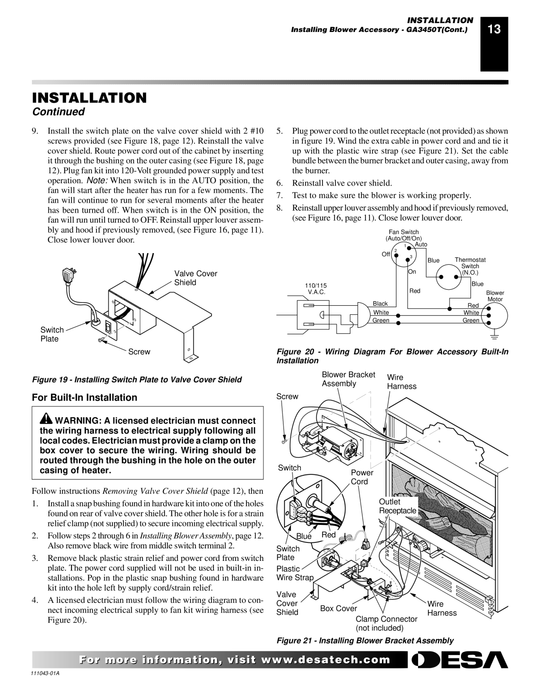
5.Plug power cord to the outlet receptacle (not provided) as shown in figure 19. Wind the extra cable in power cord and and tie it up with the plastic wire strap (see Figure 21). Set the cable bundle between the burner bracket and outer casing, away from the burner.

6.Reinstall valve cover shield.

7.Test to make sure the blower is working properly.

8.Reinstall upper louver assembly and hood if previously removed, (see Figure 16, page 11). Close lower louver door.


Fan Switch


(Auto/Off/On)


1 Auto


Off

2


3

Blue


Thermostat


On


Switch


(N.O.)

110/115


Red


Blue

V.A.C.


Blower


Black


Motor


Red


White


White


Green


Green

Figure 20 - Wiring Diagram For Blower Accessory Built-In Installation

Figure 19 - Installing Switch Plate to Valve Cover Shield

For Built-In Installation

WARNING: A licensed electrician must connect the wiring harness to electrical supply following all local codes. Electrician must provide a clamp on the box cover to secure the wiring. Wiring should be routed through the bushing in the hole on the outer casing of heater.

Follow instructions Removing Valve Cover Shield (page 12), then

1.Install a snap bushing found in hardware kit into one of the holes found on rear of valve cover shield. The other hole is for a strain relief clamp (not supplied) to secure incoming electrical supply.

2.Follow steps 2 through 6 in Installing Blower Assembly, page 12. Also remove black wire from middle switch terminal 2.

3.Remove black plastic strain relief and power cord from switch plate. The power cord supplied will not be used in built-in in- stallations. Pop in the plastic snap bushing found in hardware kit into the hole left by supply cord/strain relief.

4.A licensed electrician must follow the wiring diagram to con- nect incoming electrical supply to fan kit wiring harness (see Figure 20).

Blower Bracket

Wire

Assembly

Harness


Screw

Switch

Power

Cord


Outlet

2

Receptacle

3


1


Blue Red

Switch

Plate

Plastic

Wire Strap

Valve


Cover

Box Cover

Wire

Shield

Harness

Clamp Connector


(not included)


Figure 21 - Installing Blower Bracket Assembly

For morevisit www..com

111043-01A

Page 13
Image 13
Vanguard Heating WMH26TNB installation manual For Built-In Installation, Outlet

WMH26TNB specifications

The Vanguard Heating WMH26TNB is a powerful and efficient heating solution designed to meet the needs of residential spaces. This heating unit stands out for its innovative technology, robust features, and reliability, making it a preferred choice for homeowners looking to maintain a comfortable environment during colder months.

One of the main features of the WMH26TNB is its impressive heating capacity. With an output that can effectively warm spaces up to 1,000 square feet, it ensures consistent and uniform heat distribution throughout the room. This makes it an ideal option for living rooms, bedrooms, and even larger areas, providing a cozy atmosphere for family gatherings and quiet evenings.

Equipped with advanced heating technology, the WMH26TNB utilizes high-efficiency heating elements that minimize energy consumption while maximizing output. This not only helps in reducing electricity bills but also contributes to environmental sustainability. The unit's Energy Star certification further underscores its commitment to energy efficiency, allowing homeowners to enjoy warmth without compromise.

Another notable characteristic of the Vanguard WMH26TNB is its user-friendly digital thermostat. This intuitive interface allows for precise temperature control and programming, enabling users to set their heating preferences with ease. The programmable functionality means that users can schedule heating times based on their daily routines, ensuring that the space is warm when they need it most, without wasting energy when it's not.

The design of the WMH26TNB is both functional and aesthetically pleasing. Its sleek, modern look allows it to blend seamlessly with various home decors. The unit is also compact, making it easy to install in tight spaces, and it features a durable housing that can withstand the rigors of daily use.

Safety is paramount in any heating appliance, and the WMH26TNB does not disappoint. It includes multiple safety features, such as overheat protection and tip-over shutoff, giving users peace of mind when the unit is in operation.

In summary, the Vanguard Heating WMH26TNB is a versatile heating solution that combines advanced technology, efficient performance, and user-friendly features. Its capacity to efficiently heat large spaces, coupled with energy-saving capabilities, makes it a reliable choice for homeowners seeking warmth and comfort. Whether for everyday use or special occasions, the WMH26TNB stands as a testament to Vanguard's commitment to quality and innovation in heating solutions.