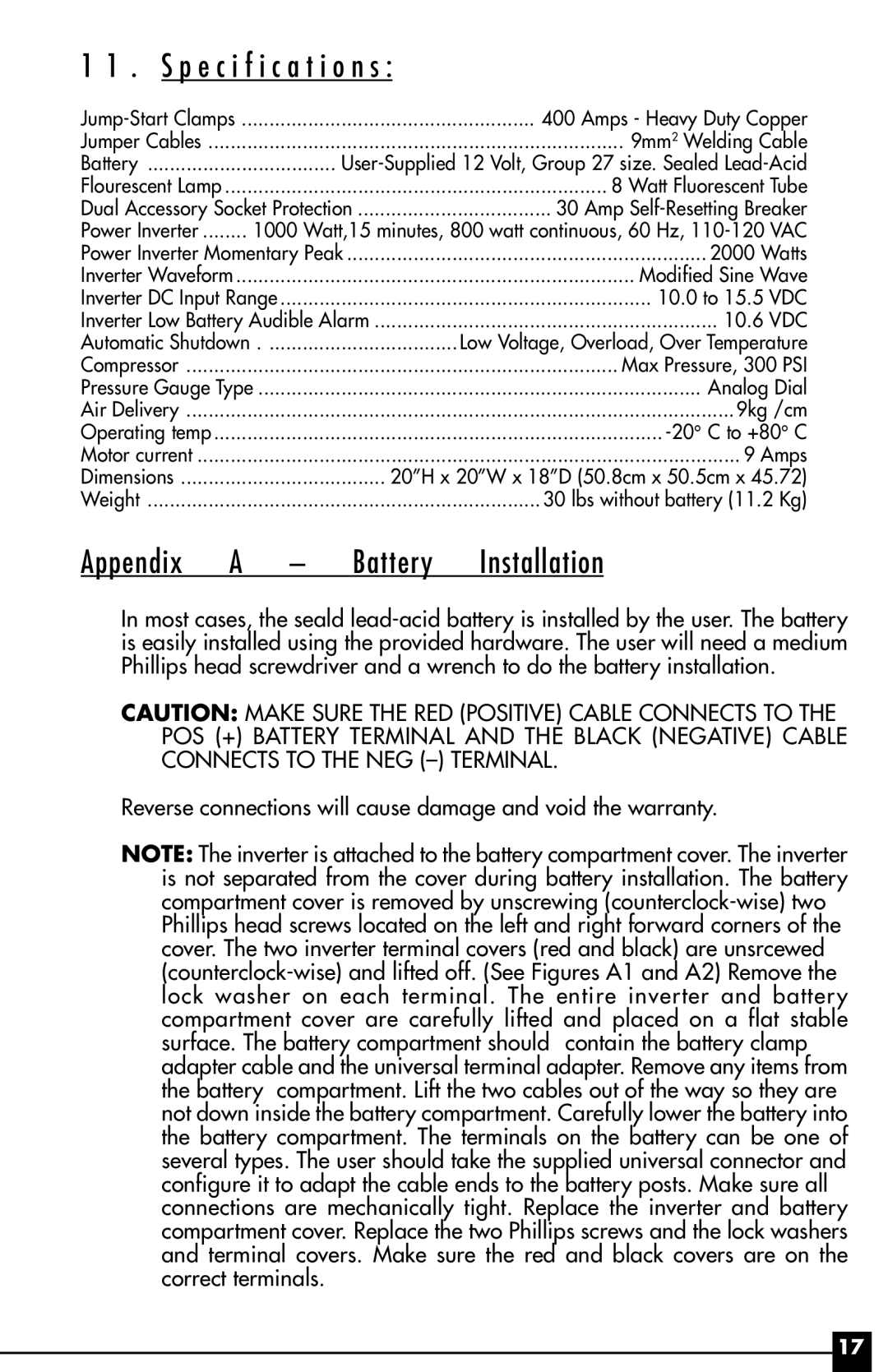
11 . S p e c i f i c a t i o n s :
Jump-Start Clamps | 400 Amps - Heavy Duty Copper |
Jumper Cables | 9mm2 Welding Cable |
Battery | User-Supplied 12 Volt, Group 27 size. Sealed Lead-Acid |
Flourescent Lamp | 8 Watt Fluorescent Tube |
Dual Accessory Socket Protection | 30 Amp Self-Resetting Breaker |
Power Inverter | 1000 Watt,15 minutes, 800 watt continuous, 60 Hz, 110-120 VAC |
Power Inverter Momentary Peak | 2000 Watts |
Inverter Waveform | Modified Sine Wave |
Inverter DC Input Range | 10.0 to 15.5 VDC |
Inverter Low Battery Audible Alarm | 10.6 VDC |
Automatic Shutdown | . .................................. | Low Voltage, Overload, Over Temperature |
Compressor | Max Pressure, 300 PSI |
Pressure Gauge Type | ................................................................................ | Analog Dial |
Air Delivery | 9kg /cm |
Operating temp | -20°C to +80° C |
Motor current | 9 Amps |
Dimensions | 20ÓH x 20ÓW x 18ÓD (50.8cm x 50.5cm x 45.72) |
Weight | 30 lbs without battery (11.2 Kg) |
Appendix A – Battery Installation
In most cases, the seald lead-acid battery is installed by the user. The battery is easily installed using the provided hardware. The user will need a medium Phillips head screwdriver and a wrench to do the battery installation.
CAUTION: MAKE SURE THE RED (POSITIVE) CABLE CONNECTS TO THE POS (+) BATTERY TERMINAL AND THE BLACK (NEGATIVE) CABLE CONNECTS TO THE NEG (Ð) TERMINAL.
Reverse connections will cause damage and void the warranty.
NOTE: The inverter is attached to the battery compartment cover. The inverter is not separated from the cover during battery installation. The battery compartment cover is removed by unscrewing (counterclock-wise) two Phillips head screws located on the left and right forward corners of the cover. The two inverter terminal covers (red and black) are unsrcewed (counterclock-wise) and lifted off. (See Figures A1 and A2) Remove the lock washer on each terminal. The entire inverter and battery compartment cover are carefully lifted and placed on a flat stable surface. The battery compartment should contain the battery clamp adapter cable and the universal terminal adapter. Remove any items from the battery compartment. Lift the two cables out of the way so they are not down inside the battery compartment. Carefully lower the battery into the battery compartment. The terminals on the battery can be one of several types. The user should take the supplied universal connector and configure it to adapt the cable ends to the battery posts. Make sure all connections are mechanically tight. Replace the inverter and battery compartment cover. Replace the two Phillips screws and the lock washers and terminal covers. Make sure the red and black covers are on the correct terminals.

