w w w . c h r y s a l i s a c o u s t i c s . c o m
(6) LED Numeric Indicator
This LED supplies information on volume, crossover, woofer type, and other information. The “light” button on the remote deactivates this display. Upon startup, the display shows the “IW”, referring to the
(7) Volume Control
These buttons allow you to balance the output from the subwoofer to the main speakers in your system. The volume should be set to achieve similar volume level of both the main speakers and subwoofer. The default volume is 30.
Note: Volume can also be controlled by using the supplied remote.
WARNING: Some manufacturers preset their receivers with the
(8) Optional Rack Mount Ears (Included)
These ears can be attached to the
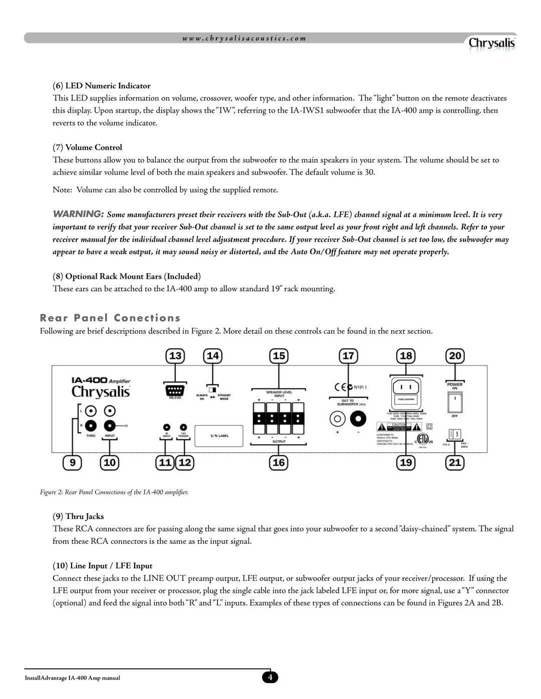
Rear Panel Conections
Following are brief descriptions described in Figure 2. More detail on these controls can be found in the next section.
Figure 2: Rear Panel Connections of the IA-400 amplifier.
(9) Thru Jacks
These RCA connectors are for passing along the same signal that goes into your subwoofer to a second
(10) Line Input / LFE Input
Connect these jacks to the LINE OUT preamp output, LFE output, or subwoofer output jacks of your receiver/processor. If using the LFE output from your receiver or processor, plug the single cable into the jack labeled LFE input or, for more signal, use a “Y” connector (optional) and feed the signal into both “R” and “L” inputs. Examples of these types of connections can be found in Figures 2A and 2B.
InstallAdvantage | 4 |