
VX-10 specifications
The Velodyne Acoustics VX-10 is a high-performance subwoofer that embodies cutting-edge design and technology, delivering a superior audio experience for both home theater enthusiasts and music lovers. Known for its compact size and powerful output, the VX-10 is an excellent choice for those seeking deep, impactful bass without sacrificing valuable living space.One of the primary features of the VX-10 is its 10-inch, long-throw driver. This driver is engineered to produce low-frequency sounds with exceptional accuracy, allowing it to reproduce bass tones in their full depth and richness. Coupled with this driver is a custom-designed amplifier that delivers 300 watts of dynamic power. This robust amplification ensures that the subwoofer can handle bursts of bass and maintain clarity even at high volumes.
Another notable aspect of the VX-10 is its advanced Digital Signal Processing (DSP) technology. This system optimizes performance by filtering and shaping the audio signal to minimize distortion and enhance sound quality. The DSP also provides controls that allow users to adjust the subwoofer’s response according to their room acoustics, ensuring that the performance fits seamlessly into any environment.
The VX-10 features a sleek and modern design, making it an attractive addition to any home audio setup. Its compact cabinet enhances its versatility, allowing it to easily blend in with furniture while still providing powerful performance. The enclosure is constructed from high-quality materials that reduce vibrations and resonance, ensuring that only pure bass is delivered.
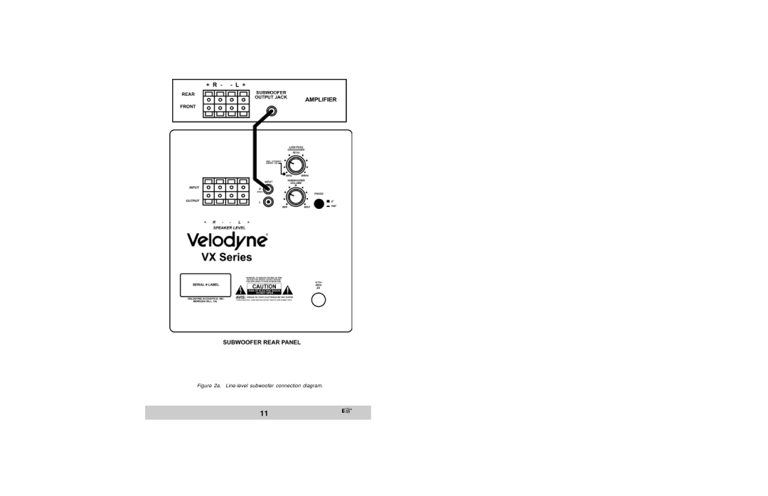
Connectivity options are abundant with the VX-10, offering both line-level and speaker-level inputs. This versatility allows it to integrate smoothly with a wide range of audio components, including receivers, amplifiers, and media players. Additionally, its phase control and variable crossover settings enable users to fine-tune their audio experience, achieving the perfect balance with their main speakers.
In summary, the Velodyne Acoustics VX-10 subwoofer stands out for its impressive combination of power, technology, and design. With its 10-inch long-throw driver, powerful amplifier, advanced DSP technology, and comprehensive connectivity options, it offers an exceptional solution for anyone looking to enhance their audio enjoyment. Whether for home theater use or music playback, the VX-10 delivers deep, accurate bass that truly elevates the listening experience.