Vermont Castings, Majestic Products, DEF33/36, DEFD33/36
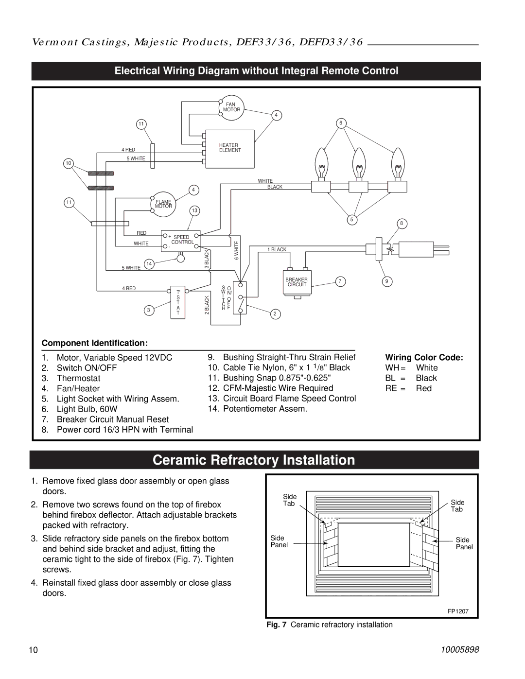
Electrical Wiring Diagram without Integral Remote Control
11 |
|
|
4 RED |
|
|
5 WHITE |
|
|
10 |
|
|
| 4 |
|
11 | FLAME |
|
| MOTOR |
|
| 13 |
|
RED | + SPEED |
|
|
| |
WHITE | CONTROL |
|
- |
| |
| BLACK | |
14 |
| |
| 3 | |
5 WHITE |
| |
|
| |
4 RED | T' |
|
| BLACK2 | |
3 | S | |
T | ||
| T |
|
| A |
|
FAN
MOTOR
HEATER ELEMENT
6 WHITE
SO WI N/
TO
CF
HF
4
6
WHITE
BLACK
5
8
1 BLACK
BREAKER | 7 | 9 |
CIRCUIT |
|
|
2
Component Identification: |
|
|
|
|
| |
1. | Motor, Variable Speed 12VDC | 9. | Bushing | Wiring Color Code: | ||
2. | Switch ON/OFF | 10. | Cable Tie Nylon, 6" x 1 1/8" Black | WH = | White | |
3. | Thermostat | 11. | Bushing Snap | BL = | Black | |
4. | Fan/Heater | 12. | RE = | Red | ||
5. | Light Socket with Wiring Assem. | 13. | Circuit Board Flame Speed Control |
|
| |
6. | Light Bulb, 60W | 14. | Potentiometer Assem. |
|
| |
7.Breaker Circuit Manual Reset
8.Power cord 16/3 HPN with Terminal
Ceramic Refractory Installation
1.Remove fixed glass door assembly or open glass doors.
2.Remove two screws found on the top of firebox behind firebox deflector. Attach adjustable brackets packed with refractory.
3.Slide refractory side panels on the firebox bottom and behind side bracket and adjust, fitting the ceramic tight to the side of firebox (Fig. 7). Tighten screws.
4.Reinstall fixed glass door assembly or close glass doors.
10
Side | Side |
Tab | |
| Tab |
Side | Side |
Panel | Panel |
| FP1207 |
Fig. 7 Ceramic refractory installation |
|
| 10005898 |