Nail Top Stand- offs
Nail Side
Nailing
Flanges
Vermont Castings EWF36A
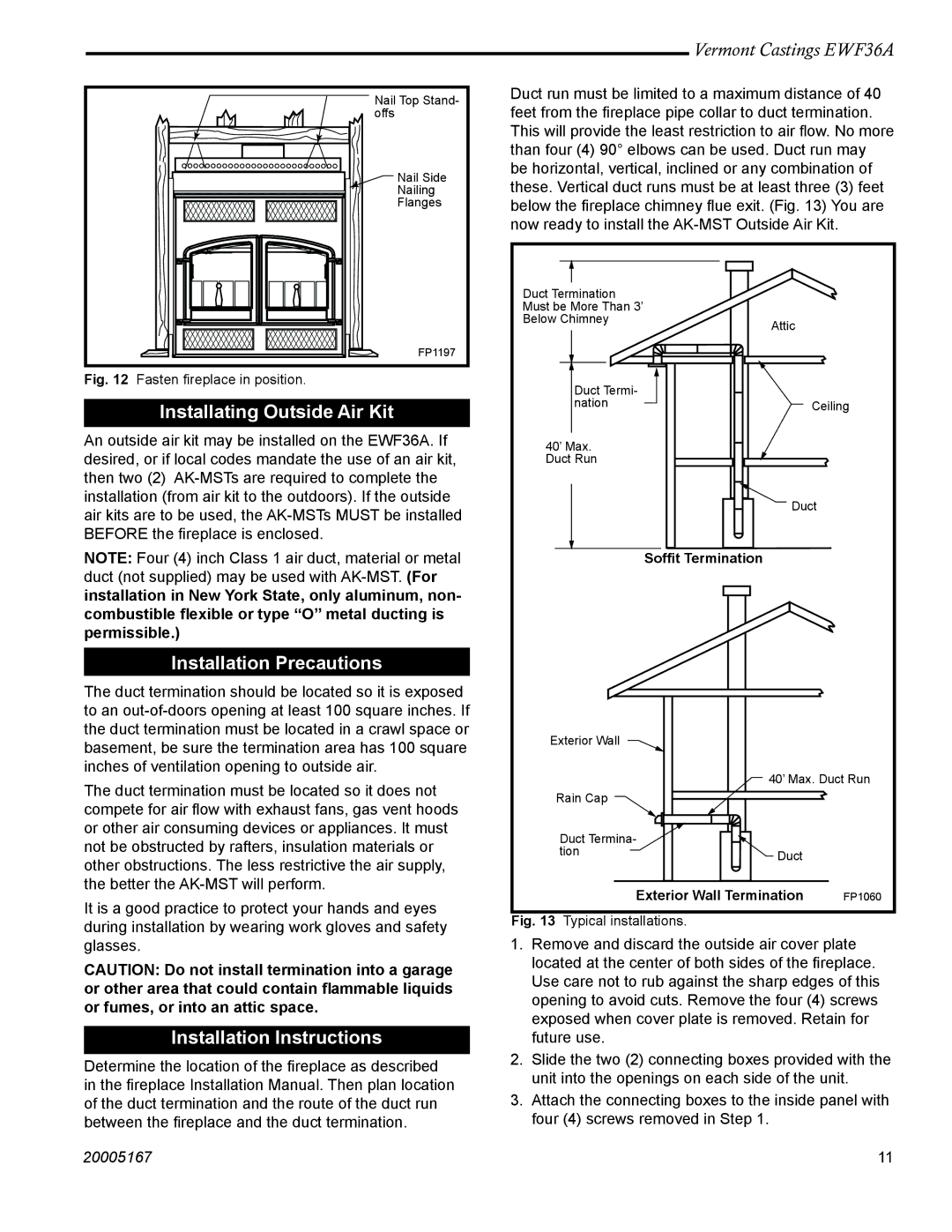
Duct run must be limited to a maximum distance of 40 feet from the fireplace pipe collar to duct termination. This will provide the least restriction to air flow. No more than four (4) 90° elbows can be used. Duct run may be horizontal, vertical, inclined or any combination of these. Vertical duct runs must be at least three (3) feet below the fireplace chimney flue exit. (Fig. 13) You are now ready to install the
FP1197
Fig. 12 Fasten fireplace in position.
Installating Outside Air Kit
An outside air kit may be installed on the EWF36A. If desired, or if local codes mandate the use of an air kit, then two (2)
Duct Termination Must be More Than 3’ Below Chimney
Duct Termi- nation
40’ Max.
Duct Run
Attic
Ceiling
air kits are to be used, the
NOTE: Four (4) inch Class 1 air duct, material or metal duct (not supplied) may be used with
Installation Precautions
The duct termination should be located so it is exposed to an
The duct termination must be located so it does not compete for air flow with exhaust fans, gas vent hoods or other air consuming devices or appliances. It must not be obstructed by rafters, insulation materials or other obstructions. The less restrictive the air supply, the better the
It is a good practice to protect your hands and eyes during installation by wearing work gloves and safety glasses.
CAUTION: Do not install termination into a garage or other area that could contain flammable liquids or fumes, or into an attic space.
Installation Instructions
Determine the location of the fireplace as described in the fireplace Installation Manual. Then plan location of the duct termination and the route of the duct run between the fireplace and the duct termination.
Duct
Soffit Termination
Exterior Wall |
|
| 40’ Max. Duct Run |
Rain Cap |
|
Duct Termina- |
|
tion | Duct |
|
Exterior Wall Termination | FP1060 |
Fig. 13 Typical installations.
1.Remove and discard the outside air cover plate located at the center of both sides of the fireplace. Use care not to rub against the sharp edges of this opening to avoid cuts. Remove the four (4) screws exposed when cover plate is removed. Retain for future use.
2.Slide the two (2) connecting boxes provided with the unit into the openings on each side of the unit.
3.Attach the connecting boxes to the inside panel with four (4) screws removed in Step 1.
20005167 | 11 |
