LHER20 specifications
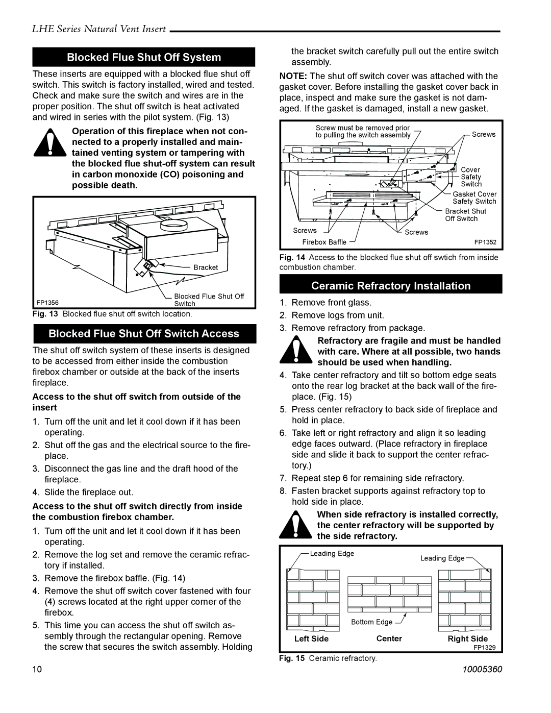
The Vermont Casting LHER20 is a premium wood-burning stove that combines efficiency, aesthetics, and environmentally responsible heating. Known for its high-quality construction and innovative technologies, this model is designed to provide optimal warmth while also enhancing any living space with its classic design.One of the standout features of the LHER20 is its exceptional thermal efficiency. With an EPA-certified design, the stove meets stringent emissions standards, ensuring that it burns wood cleanly and efficiently. This not only helps in reducing environmental impact but also translates to longer burn times and less frequent reloading, providing convenience for users.
The LHER20 incorporates advanced air management systems that promote secondary combustion. This technology re-burns exit gases from the initial burn, maximizing fuel utilization and enhancing heat output. As a result, this stove delivers a remarkable heat output, making it ideal for heating medium to large spaces.
Crafted from high-quality cast iron, the Vermont Casting LHER20 offers both durability and aesthetic appeal. It comes in several attractive finishes, including matte black and classic enamel colors, allowing homeowners to choose a look that complements their decor. The traditional styling features large glass doors that provide a captivating view of the fire, creating a cozy atmosphere and enhancing the overall experience of wood-burning.
Another notable characteristic is its user-friendly operation. The LHER20 features a simple damper control system, allowing users to easily adjust airflow for controlling the burn rate. This ensures a steady and consistent heat output while allowing users to tailor the stove’s performance to their preferences.
In terms of size, the LHER20 is compact yet powerful, making it suitable for various spaces, including cabins, homes, or even larger open-plan areas. The stove's efficient heat delivery helps create a comfortable environment during the cold months, proving its worth as a reliable heating solution.
Overall, the Vermont Casting LHER20 is an exemplary wood stove that combines tradition with modern technology. Its outstanding features, environmental responsibility, and aesthetic appeal make it a sought-after choice for those seeking to embrace the warmth and charm of wood-burning stoves in their homes. Whether for aesthetics, efficiency, or performance, the LHER20 stands as a testament to Vermont Casting's commitment to quality.

