6a |
|
|
| 6b |
| 6c |
|
| Ceiling |
|
| Without Hood |
|
| |
|
|
|
|
|
| With Hood |
|
| Noncombus- |
|
|
|
|
| |
| tible Facing |
| 42” Min. |
|
|
|
|
| Material | 4¹⁄₂” |
| Noncombustible |
|
|
|
|
|
| Material |
|
|
| |
|
| Min. |
|
|
|
| |
|
|
|
|
|
|
| |
|
|
|
| Standoff | 38¹⁄₂” | 8” |
|
|
|
|
|
|
| ||
|
|
|
|
|
| Flat Man- | |
|
|
|
|
| 20” |
| |
|
|
|
|
|
| tel Shelf | |
|
|
|
|
|
|
| |
|
|
|
| 2¹⁄₂” |
| 2¹⁄₂” | 7¹⁄₄” |
|
|
|
|
|
| ||
|
|
|
|
|
| 6³⁄₄” | |
| 4¹⁄₂” |
|
|
|
|
| |
| Min. |
|
|
|
|
|
|
| Front View |
|
|
|
|
| |
| Finished Wall Material |
|
|
| 4” Hood | ||
|
|
| Mantel |
|
|
| |
|
|
|
|
|
|
| |
|
|
| Trim |
|
|
| Seal With |
| Firebox |
|
|
|
| Noncombustible | |
|
|
|
|
|
|
| Material |
|
|
|
| Front | 3¹⁄₄” - VL18 |
|
|
|
|
|
| Edge of |
|
| |
|
|
|
| 5¹⁄₄” - VL21, VL24 |
|
| |
4¹⁄₂” |
|
| 4¹⁄₂” | Grate |
|
| |
|
|
|
|
| |||
Min. |
|
| Min. |
|
|
|
|
Mantel | Noncombustible |
|
|
|
| ||
Trim |
|
|
|
|
| ||
|
| Facing Material |
|
|
|
| |
| Top View |
|
| MC609 | |||
|
|
|
|
| |||
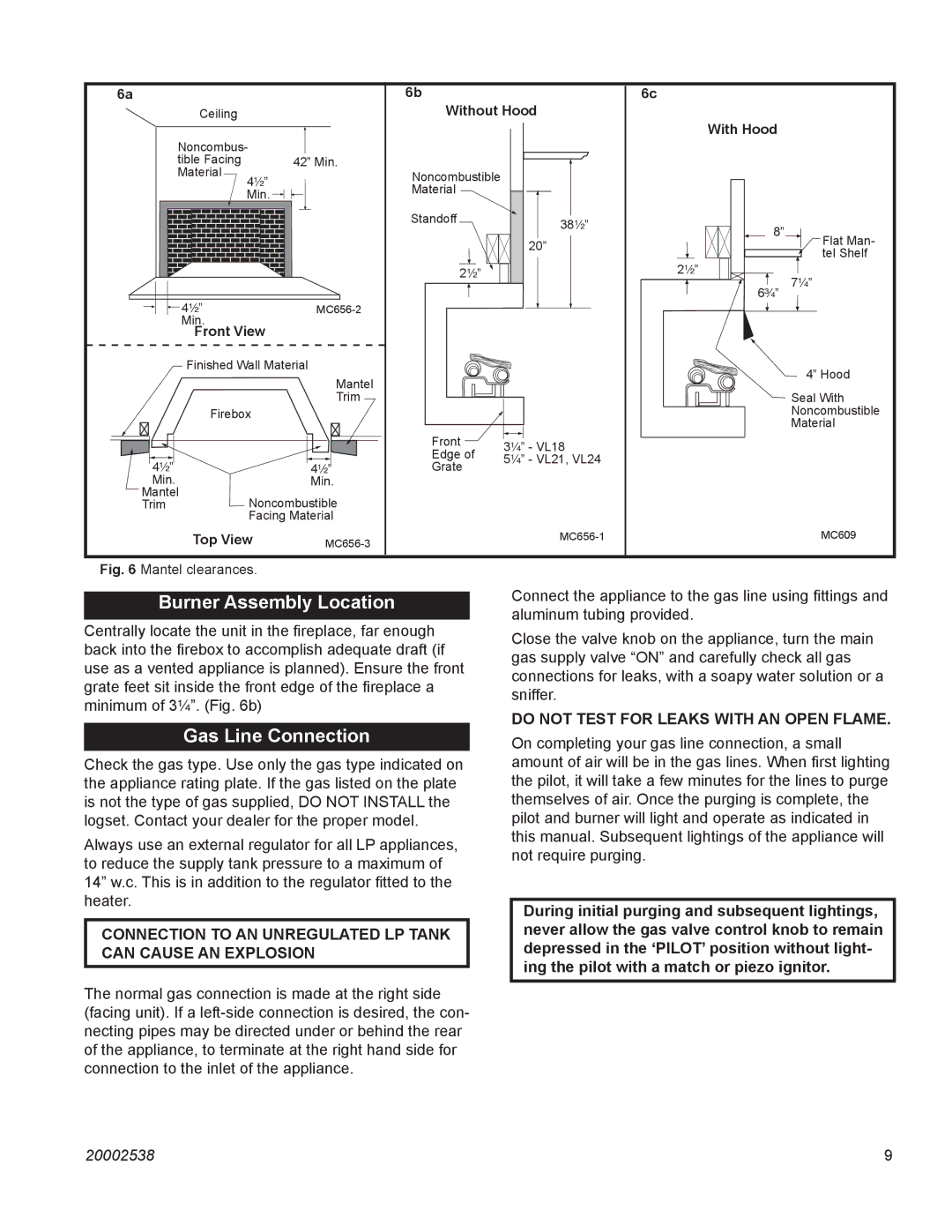
Fig. 6 Mantel clearances.
Burner Assembly Location
Centrally locate the unit in the fireplace, far enough back into the firebox to accomplish adequate draft (if use as a vented appliance is planned). Ensure the front grate feet sit inside the front edge of the fireplace a minimum of 3¹⁄₄”. (Fig. 6b)
Gas Line Connection
Check the gas type. Use only the gas type indicated on the appliance rating plate. If the gas listed on the plate is not the type of gas supplied, DO NOT INSTALL the logset. Contact your dealer for the proper model.
Always use an external regulator for all LP appliances, to reduce the supply tank pressure to a maximum of 14” w.c. This is in addition to the regulator fitted to the heater.
CONNECTION TO AN UNREGULATED LP TANK CAN CAUSE AN EXPLOSION
The normal gas connection is made at the right side (facing unit). If a
Connect the appliance to the gas line using fittings and aluminum tubing provided.
Close the valve knob on the appliance, turn the main gas supply valve “ON” and carefully check all gas connections for leaks, with a soapy water solution or a sniffer.
DO NOT TEST FOR LEAKS WITH AN OPEN FLAME.
On completing your gas line connection, a small amount of air will be in the gas lines. When first lighting the pilot, it will take a few minutes for the lines to purge themselves of air. Once the purging is complete, the pilot and burner will light and operate as indicated in this manual. Subsequent lightings of the appliance will not require purging.
During initial purging and subsequent lightings, never allow the gas valve control knob to remain depressed in the ‘PILOT’ position without light- ing the pilot with a match or piezo ignitor.
20002538 | 9 |