LEVELLING THE RANGE
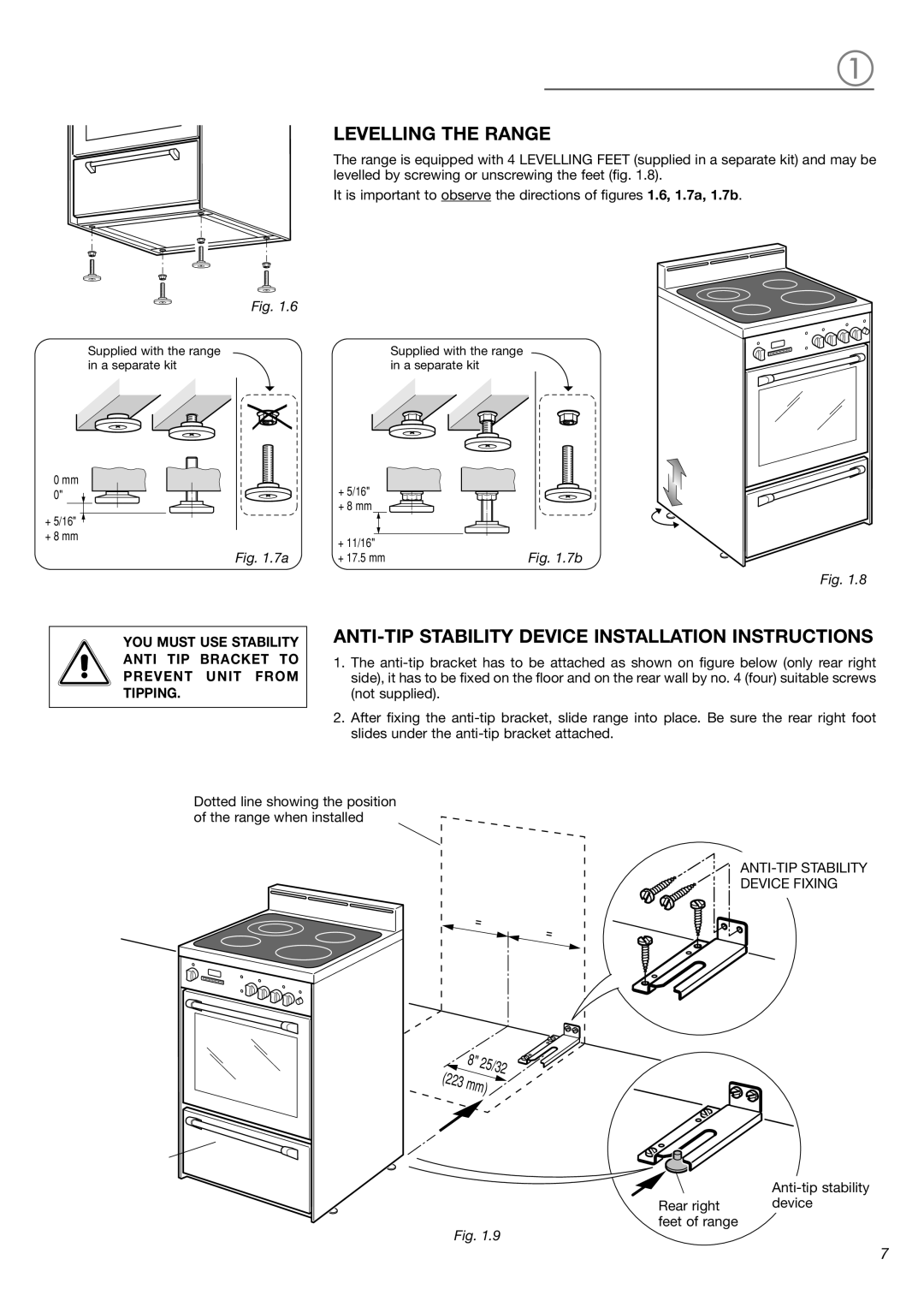
The range is equipped with 4 LEVELLING FEET (supplied in a separate kit) and may be levelled by screwing or unscrewing the feet (fig. 1.8).
It is important to observe the directions of figures 1.6, 1.7a, 1.7b.
Fig. 1.6
Supplied with the range in a separate kit
0 mm 0"
+5/16" ![]()
+8 mm
Fig. 1.7a
YOU MUST USE STABILITY
ANTI TIP BRACKET TO
PREVENT UNIT FROM
TIPPING.
Supplied with the range in a separate kit
+ 5/16" + 8 mm
+ 11/16" | Fig. 1.7b |
+ 17.5 mm |
Fig. 1.8
ANTI-TIP STABILITY DEVICE INSTALLATION INSTRUCTIONS
1.The
2.After fixing the
Dotted line showing the position of the range when installed
=
DEVICE FIXING
=
(223
8" | 25/32 |
mm) | |
Rear right device feet of range
Fig. 1.9
7