Alignment
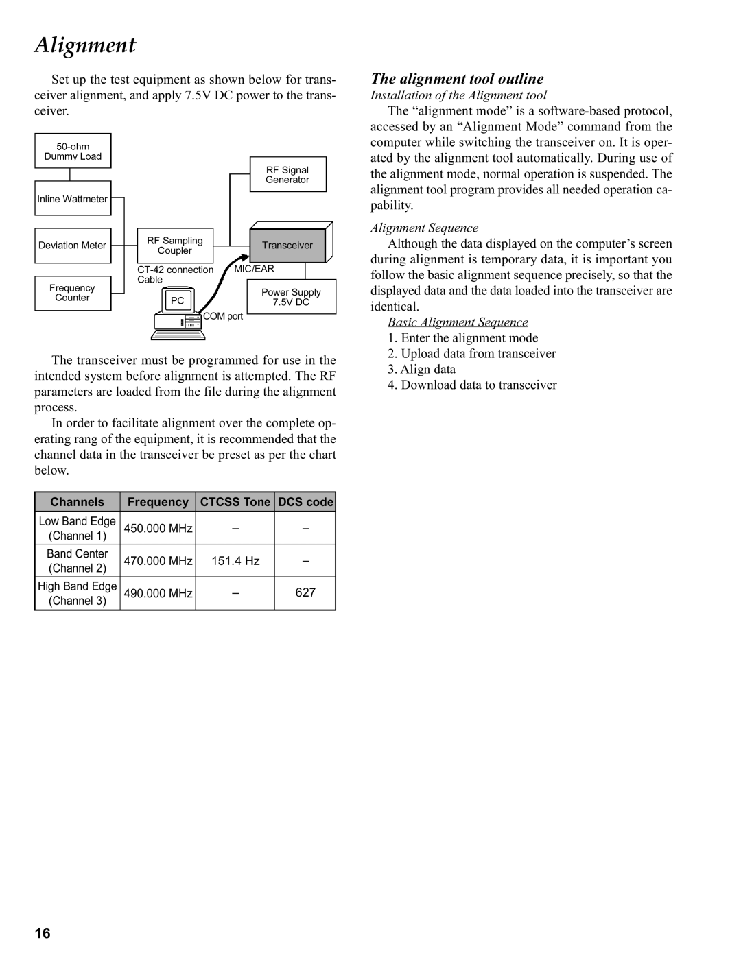
Set up the test equipment as shown below for trans- ceiver alignment, and apply 7.5V DC power to the trans- ceiver.
|
|
| RF Signal |
|
|
| Generator |
Inline Wattmeter |
|
|
|
| RF Sampling |
|
|
Deviation Meter |
| Transceiver | |
Coupler |
| ||
|
|
| |
|
|
|
|
| MIC/EAR | ||
Frequency | Cable |
|
|
|
| Power Supply | |
Counter | PC |
| |
| 7.5V DC | ||
|
| ||
COM port
The transceiver must be programmed for use in the intended system before alignment is attempted. The RF parameters are loaded from the file during the alignment process.
In order to facilitate alignment over the complete op- erating rang of the equipment, it is recommended that the channel data in the transceiver be preset as per the chart below.
Channels | Frequency | CTCSS Tone | DCS code |
Low Band Edge | 450.000 MHz | – | – |
(Channel 1) |
|
|
|
Band Center | 470.000 MHz | 151.4 Hz | – |
(Channel 2) |
|
|
|
High Band Edge | 490.000 MHz | – | 627 |
(Channel 3) |
|
|
|
The alignment tool outline
Installation of the Alignment tool
The “alignment mode” is a
Alignment Sequence
Although the data displayed on the computer’s screen during alignment is temporary data, it is important you follow the basic alignment sequence precisely, so that the displayed data and the data loaded into the transceiver are identical.
Basic Alignment Sequence
1.Enter the alignment mode
2.Upload data from transceiver
3.Align data
4.Download data to transceiver
16