ENGESBRA Distribuidor Autorizado Vertex Standard
Alignment
Test Setup
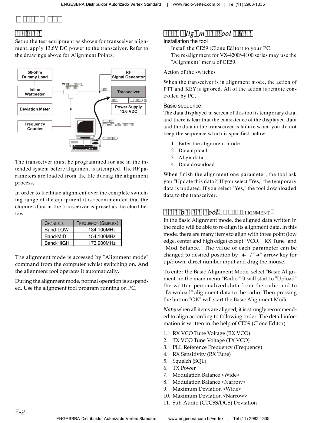
Setup the test equipment as shown for transceiver align- ment, apply 13.6V DC power to the transceiver. Refer to the drawings above for Alignment Points.
The Alignment Tool Outline
Installation the tool
Install the CE59 (Clone Editor) to your PC.
The
Dummy Load
RF Sampling
RF
Signal Generator
Action of the switches
When the transceiver is in alignment mode, the action of
Inline
Coupler
ANT
Transceiver
PTT and KEY is ignored. All of the action is remote con-
Wattmeter
Deviation Meter ![]()
Frequency
Counter
MIC | DC INPUT |
|
|
Power Supply
13.6 VDC
Connection Cable
trolled by PC.
Basic sequence
The data displayed in screen of this tool is temporary data, and there is fear that the consistence of the displayed data and the data in the transceiver is failure when you do not keep the sequence which is specified below.
COM Port
The transceiver must be programmed for use in the in- tended system before alignment is attempted. The RF pa- rameters are loaded from the file during the alignment process.
In order to facilitate alignment over the complete switch- ing range of the equipment it is recommended that the channel data in the transceiver is preset as the chart be- low.
CHANNELS | FREQUENCY (SIMPLEX) |
134.100MHz | |
154.100MHz | |
173.900MHz |
The alignment mode is accessed by "Alignment mode" command from the computer whilst switching on. And the alignment tool operates it automatically.
During the alignment mode, normal operation is suspend- ed. Use the alignment tool program running on PC.
1.Enter the alignment mode
2.Data upload
3.Align data
4.Data download
When finish the alignment one parameter, the tool ask you "Update this data?" If you select "Yes," the temporary data is updated. If you select "Yes," the tool downloaded data to the transceiver.
Menu of the Tool (BASIC ALIGNMENT)
In the Basic Alignment mode, the aligned data written in the radio will be able to
To enter the Basic Alignment Mode, select "Basic Align- ment" in the main menu "Radio." It will start to "Upload" the written personalized data from the radio and to "Download" alignment data to the radio. Then pressing the button "OK" will start the Basic Alignment Mode.
Note; when all items are aligned, it is strongly recommend- ed to align according to following order. The detail infor- mation is written in the help of CE59 (Clone Editor).
1.RX VCO Tune Voltage (RX VCO)
2.TX VCO Tune Voltage (TX VCO)
3.PLL Reference Frequency (Frequency)
4.RX Sensitivity (RX Tune)
5.Squelch (SQL)
6.TX Power
7.Modulation Balance <Wide>
8.Modulation Balance <Narrow>
9.Maximum Deviation <Wide>
10.Maximum Deviation <Narrow>
11.
ENGESBRA Distribuidor Autorizado Vertex Standard www.engesbra.com.br/vertex Tel.(11)