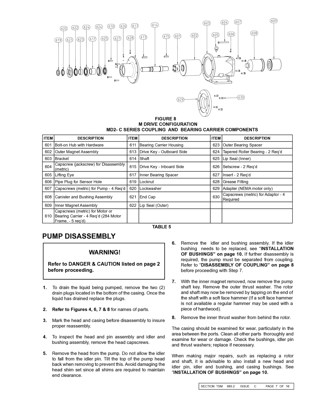
FIGURE 8

M DRIVE CONFIGURATION

MD2- c SERIES COUPLING and BEARING CARRIER COMPONENTS

ITEM

DESCRIPTION

ITEM

DESCRIPTION

ITEM

DESCRIPTION

601

Bolt-on Hub with Hardware

611

Bearing Carrier Housing

623

Outer Bearing Spacer

602

Outer Magnet Assembly

613

Drive Key - Outboard Side

624

Tapered Roller Bearing - 2 Req’d

603

Bracket

614

Shaft

625

Lip Seal (Inner)

604

Capscrew (jackscrew) for Disassembly

615

Drive Key - Inboard Side

626

Setscrew - 2 Req’d

(metric)

605

Lifting Eye

617

Inner Bearing Spacer

627

Insert - 2 Req’d

606

Pipe Plug for Sensor Hole

619

Locknut

628

Grease Fitting

607

Capscrews (metric) for Pump - 4 Req’d

620

Lockwasher

629

Adapter (NEMA motor only)

608

Canister and Bushing Assembly

621

End Cap

630

Capscrews (metric) for Adaptor - 4


Required

609

Inner Magnet Assembly

622

Lip Seal (Outer)


Capscrews (metric) for Motor or


610

Bearing Carrier - 4 Req’d (284 Motor


Frame, - 5 req’d)


Table 5

PUMP DISASSEMBLY

WARNING!

Refer to DANGER & CAUTION listed on page 2 before proceeding.

1.To drain the liquid being pumped, remove the two (2) drain plugs located in the bottom of the casing. Once the liquid has drained replace the plugs.

2.Refer to Figures 4, 6, 7 & 8 for names of parts.

3.Mark the head and casing before disassembly to insure proper reassembly.

4.To inspect the head and pin assembly and idler and bushing assembly, remove the head capscrews.

5.Remove the head from the pump. Do not allow the idler to fall from the idler pin. Tilt the top of the pump head back when removing to prevent this. Avoid damaging the head shim set since all shims are required to maintain end clearance.

6.Remove the idler and bushing assembly. If the idler bushing needs to be replaced, see “INSTALLATION OF BUSHINGS” on page 10. If further disassembly is required, the pump must be separated from coupling. Refer to “DISASSEMBLY OF COUPLING” on page 8 before proceeding with Step 7.

7.With the inner magnet removed, now remove the pump shaft key. Remove the outer thrust washer. The rotor and shaft may now be removed by tapping on the end of the shaft with a soft face hammer (If a soft face hammer is not available a regular hammer may be used with a piece of hardwood).

8. Remove the inner thrust washer from behind the rotor.

The casing should be examined for wear, particularly in the area between the ports. Clean all other parts thoroughly and examine for wear or damage. Check the bushings, idler pin and thrust washers; replace if necessary.

When making major repairs, such as replacing a rotor and shaft, it is advisable to also install a new head and idler pin, idler and bushing, and casing bushings. See “INSTALLATION OF BUSHINGS” on page 10.

SECTION TSM 685.2 ISSUE C

PAGE OF 16


Page 7
Image 7
Viking 855 service manual Pump Disassembly, MD2- c Series Coupling and Bearing Carrier Components

855 specifications

The Viking 855 is a remarkable addition to the family of high-performance, versatile amphibious vehicles designed for a variety of terrains and demanding environments. Known for its robustness and reliability, the Viking 855 combines advanced engineering with practical functionality, making it an ideal choice for both commercial and recreational applications.

One of the defining features of the Viking 855 is its powerful engine, which provides impressive torque and acceleration. This vehicle is typically equipped with a diesel engine that emphasizes fuel efficiency without sacrificing performance. The engine's design contributes to a lower environmental impact, making the Viking 855 suitable for operations in sensitive areas.

The Viking 855 stands out with its distinctive all-terrain capabilities, allowing it to navigate through mud, snow, sand, and water with ease. Its amphibious nature is enhanced by a well-engineered hull, which not only helps it float but also allows for smooth transitions from land to water and vice versa. This makes the Viking 855 an excellent choice for search and rescue operations, construction sites, and recreational outings where access to challenging terrains is a requirement.

One of the key technologies implemented in the Viking 855 is its hydraulic system, which powers its steering and braking mechanisms. This system ensures precise control and responsiveness, even in difficult conditions. The Viking 855 also features a high ground clearance, advanced suspension, and robust tires, further enhancing its off-road capabilities.

Safety is a crucial feature of the Viking 855, with attention paid to stability and passenger protection. The vehicle typically includes multiple seat belts and reinforced cabins, ensuring that occupants remain secure even in tumultuous environments. Additionally, the Viking 855 is designed to meet industry standards for durability and safety.

The Viking 855 boasts a spacious and modular interior, which can be configured for various uses, from transporting personnel to carrying cargo. This flexibility extends to its load-carrying capabilities, making it a useful vehicle for logistical operations.

In summary, the Viking 855 is an exceptional vehicle that fuses power, efficiency, and adaptability. Its advanced features and capabilities make it a top-tier choice for those needing reliable transport across diverse landscapes, ensuring it remains an attractive option for commercial users and adventure seekers alike.