VENTILATION
Dimensions & Specifications
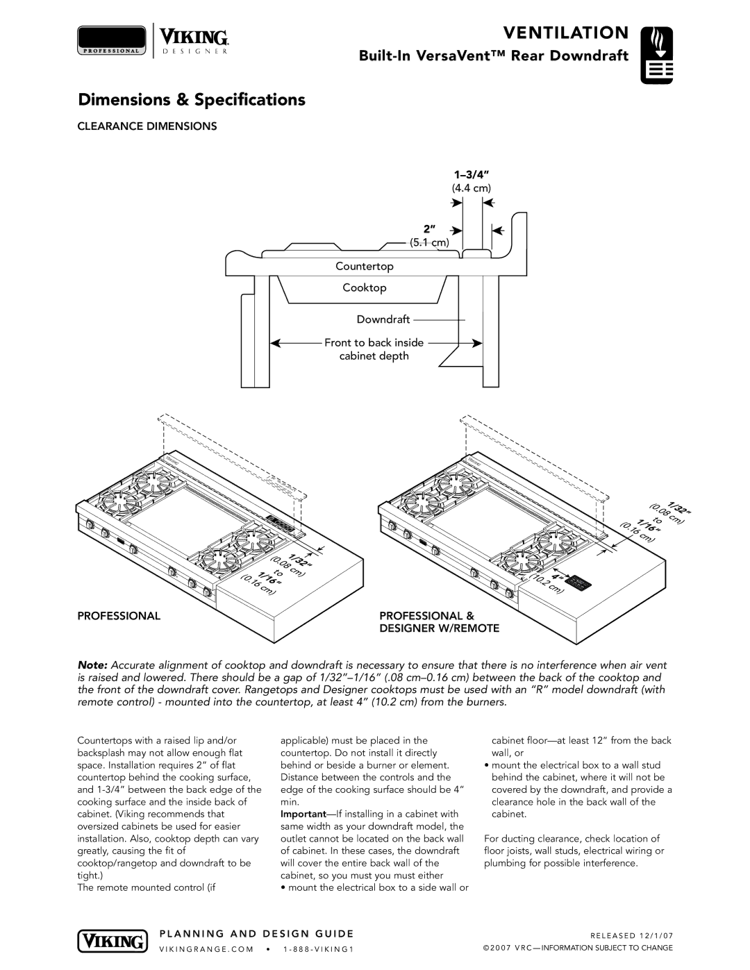
CLEARANCE DIMENSIONS
(4.4 cm)
2”
(5.1 cm)
Countertop
Cooktop
Downdraft
![]() Front to back inside
Front to back inside ![]() cabinet depth
cabinet depth
| 081/32” | |
| (0. | cm) |
| to | |
(0 | 161/16” |
|
| . |
|
| c |
|
| m) |
|
PROFESSIONAL |
| PROFESSIONAL & |
|
| DESIGNER W/REMOTE |
| 081/32” | |
| (0. | cm) |
| to | |
(0 | 161/16” |
|
| . |
|
| cm) |
|
(10 | . |
| 4” | 1 |
|
|
| 2 | |
| 2 |
| 3 | |
|
| cm) | 4 | |
Note: Accurate alignment of cooktop and downdraft is necessary to ensure that there is no interference when air vent is raised and lowered. There should be a gap of
Countertops with a raised lip and/or backsplash may not allow enough flat space. Installation requires 2” of flat countertop behind the cooking surface, and
The remote mounted control (if
applicable) must be placed in the countertop. Do not install it directly behind or beside a burner or element. Distance between the controls and the edge of the cooking surface should be 4” min.
• mount the electrical box to a side wall or
cabinet
•mount the electrical box to a wall stud behind the cabinet, where it will not be covered by the downdraft, and provide a clearance hole in the back wall of the cabinet.
For ducting clearance, check location of floor joists, wall studs, electrical wiring or plumbing for possible interference.
P L A N N I N G A N D D E S I G N G U I D E | R E L E A S E D 1 2 / 1 / 0 7 |
V I K I N G R A N G E . C O M • 1 - 8 8 8 - V I K I N G 1 | © 2 0 0 7 V R C — INFORMATION SUBJECT TO CHANGE |