E3100 Final Assembly
NOTE: Assembly Steps 7, 8 and 9 refer to Model E3100 only. For Models E3200/E3200HRC proceed to Step 10 for Console installation.
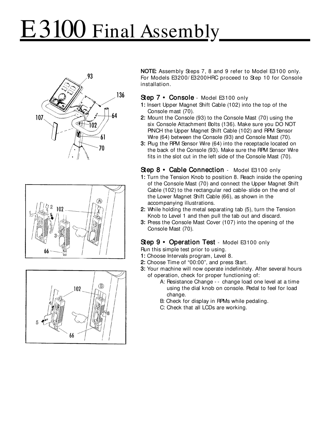
Step 7 • Console - Model E3100 only
1:Insert Upper Magnet Shift Cable (102) into the top of the Console mast (70).
2:Mount the Console (93) to the Console Mast (70) using the six Console Attachment Bolts (136). Make sure you DO NOT PINCH the Upper Magnet Shift Cable (102) and RPM Sensor Wire (64) between the Console (93) and Console Mast (70).
3:Plug the RPM Sensor Wire (64) into the receptacle located on the back of the Console (93). Make sure the RPM Sensor Wire fits in the slot cut in the left side of the Console Mast (70).
Step 8 • Cable Connection - Model E3100 only
1:Turn the Tension Knob to position 8. Reach inside the opening of the Console Mast (70) and connect the Upper Magnet Shift Cable (102) to the rectangular red
2:While holding the metal separating tab (5), turn the Tension Knob to Level 1 and then pull the tab out and discard.
3:Press the Console Mast Cover (107) into the opening of the Console Mast (70).
Step 9 • Operation Test - Model E3100 only
Run this simple test prior to using.
1:Choose Intervals program, Level 8.
2:Choose Time of “00:00”, and press Start.
3:Your machine will now operate indefinitely. After several hours of operation, check for proper functioning of:
A:Resistance Change
B:Check for display in RPMs while pedaling.
C:Check that all LCDs are working.