E3200 Final Assembly
NOTE: Assembly Steps 10 and 11 refer to Models
E3200/E3200HRC only.
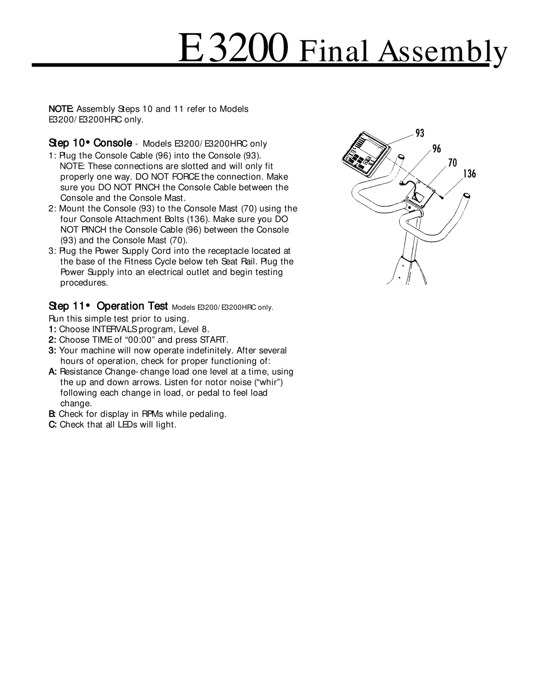
Step 10•Console - Models E3200/E3200HRC only
1:Plug the Console Cable (96) into the Console (93). NOTE: These connections are slotted and will only fit properly one way. DO NOT FORCE the connection. Make sure you DO NOT PINCH the Console Cable between the Console and the Console Mast.
2:Mount the Console (93) to the Console Mast (70) using the four Console Attachment Bolts (136). Make sure you DO NOT PINCH the Console Cable (96) between the Console (93) and the Console Mast (70).
3:Plug the Power Supply Cord into the receptacle located at the base of the Fitness Cycle below teh Seat Rail. Plug the Power Supply into an electrical outlet and begin testing procedures.
Step 11• Operation Test Models E3200/E3200HRC only.
Run this simple test prior to using.
1:Choose INTERVALS program, Level 8.
2:Choose TIME of “00:00” and press START.
3:Your machine will now operate indefinitely. After several hours of operation, check for proper functioning of:
A:Resistance
B:Check for display in RPMs while pedaling.
C:Check that all LEDs will light.