A s s e m b l y G u i d e
X6000
ELLIPTICAL TRAINER
To avoid possible damage to this Elliptical Trainer, please follow these assembly steps in the correct order. Before proceeding, find your new Elliptical Trainer’s serial number located on the front axle tube, and enter here:
Refer to this number when calling for service, and enter this serial number on your Warranty Card and in your own records. Be sure to read your Owner’s Guide before using your new Elliptical Trainer.
If any parts, hardware or tools are missing, please call 1.800.335.4348
NOTE: It is recommended that you apply grease to the threads of each screw as you assemble your Elliptical Trainer to prevent loosening and noise. Also, during each assembly step, ensure that ALL screws are in place and partially threaded in before completely tightening any ONE screw.
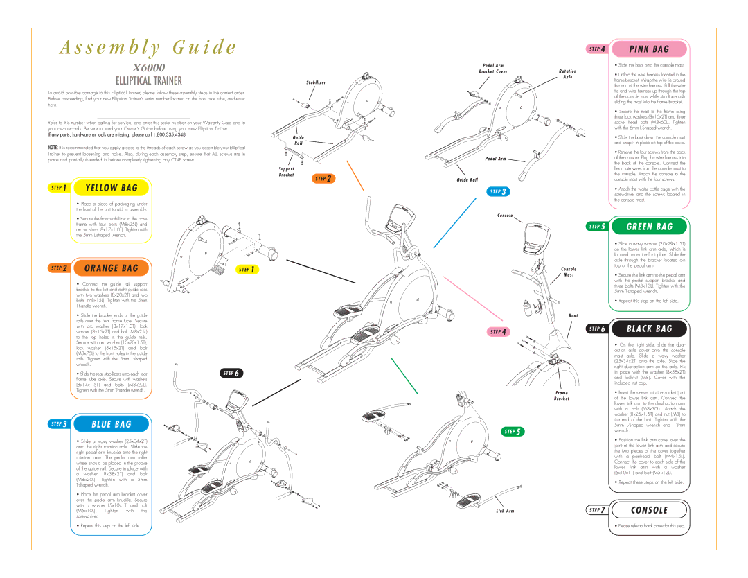
S T E P 1 YELLOW BAG
•Place a piece of packaging under the front of the unit to aid in assembly.
•Secure the front stabilizer to the base
Stabilizer
Guide
Rail
Support
Bracket
S T E P 2
Pedal Arm
Bracket Cover
Pedal Arm
Guide Rail
S T E P 3
Console
S T E P 4 | PINK BAG |
• Slide the boot onto the console mast.
Rotation
Axle• Unfold the wire harness located in the frame bracket. Wrap the wire tie around
the end of the wire harness. Pull the wire tie and wire harness up through the top of the console mast while simultaneously sliding the mast into the frame bracket.
•Secure the mast to the frame using three lock washers (8x15x2T) and three socket head bolts (M8x60L). Tighten with the 6mm
• Slide the boot down the console mast and snap it in place on top of the cover.
•Remove the four screws from the back of the console. Plug the wire harness into the back of the console. Connect the heart rate wires from the console mast to the console. Attach the console to the console mast with the four screws.
•Attach the water bottle cage with the screwdriver and the screws located in the console mast.
frame with four bolts (M8x25L) and arc washers (8x17x1.0T). Tighten with the 5mm
S T E P 2 | ORANGE BAG | S T E P 1 |
• Connect the guide rail support |
bracket to the left and right guide rails |
with two washers (8x20x2T) and two |
bolts (M8x15L). Tighten with the 5mm |
• Slide the bracket ends of the guide |
rails over the rear frame tube. Secure |
with arc washer (8x17x1.0T), lock |
washer (8x15x2T) and bolt (M8x25L) |
to the top holes in the guide rails. |
Secure with arc washer (10x20x1.5T), |
S T E P 4
S T E P
Console
Mast
Boot
S T E P
5
6
GREEN BAG
•Slide a wavy washer (20x29x1.5T) on the lower link arm axle, which is located under the foot plate. Slide the axle through the bracket located
•Secure the link arm to the pedal arm with the pedal support bracket and three bolts (M8x13L). Tighten with the 5mm
•Repeat this step on the left side.
BLACK BAG
lock washer (8x15x2T) and bolt |
(M8x75L) to the front holes in the guide |
rails. Tighten with the 5mm |
wrench. |
• Slide the rear stabilizers onto each rear | S T E P 6 |
frame tube axle. Secure with washers |
|
(8x14x1.5T) and bolts (M8x20L). |
|
Tighten with the 5mm |
|
S T E P 3 | BLUE BAG |
• Slide a wavy washer (25x34x2T) onto the right rotation axle. Slide the right pedal arm knuckle onto the right rotation axle. The pedal arm roller wheel should be placed in the groove of the guide rail. Secure in place with a washer (8x38x2T) and bolt (M8x20L). Tighten with a 5mm
•Place the pedal arm bracket cover over the pedal arm knuckle. Secure with a washer (5x10x1T) and bolt (M5x10L). Tighten with the screwdriver.
•Repeat this step on the left side.
S T E P 5
Link Arm
| • On the right side, slide the dual- |
| action axle cover onto the console |
| mast axle. Slide a wavy washer |
| (25x34x2T) onto the axle. Slide the |
| right |
| in place with the washer (8x38x2T) |
| and locknut (M8). Cover with the |
| included nut cap. |
Frame | • Insert the sleeve into the socket joint |
Bracket | of the lower link arm. Connect the |
| lower link arm to the dual action arm |
| with a bolt (M8x30L). Attach the |
| washer (8x25x1.5T) and nut (M8) to |
| the end of the bolt. Tighten with the |
| 5mm |
| wrench. |
| • Position the link arm cover over the |
| joint of the lower link arm and secure |
| the two pieces of the cover together |
| with a panhead bolt (M4x15L). |
| Connect the cover to each side of the |
| lower link arm with a washer |
| (5x10x1T) and bolt (M5x12L). |
| • Repeat these steps on the left side. |
S T E P 7 | CONSOLE |
| • Please refer to back cover for this step. |