Appendix A Power Supply Specifications
300 W
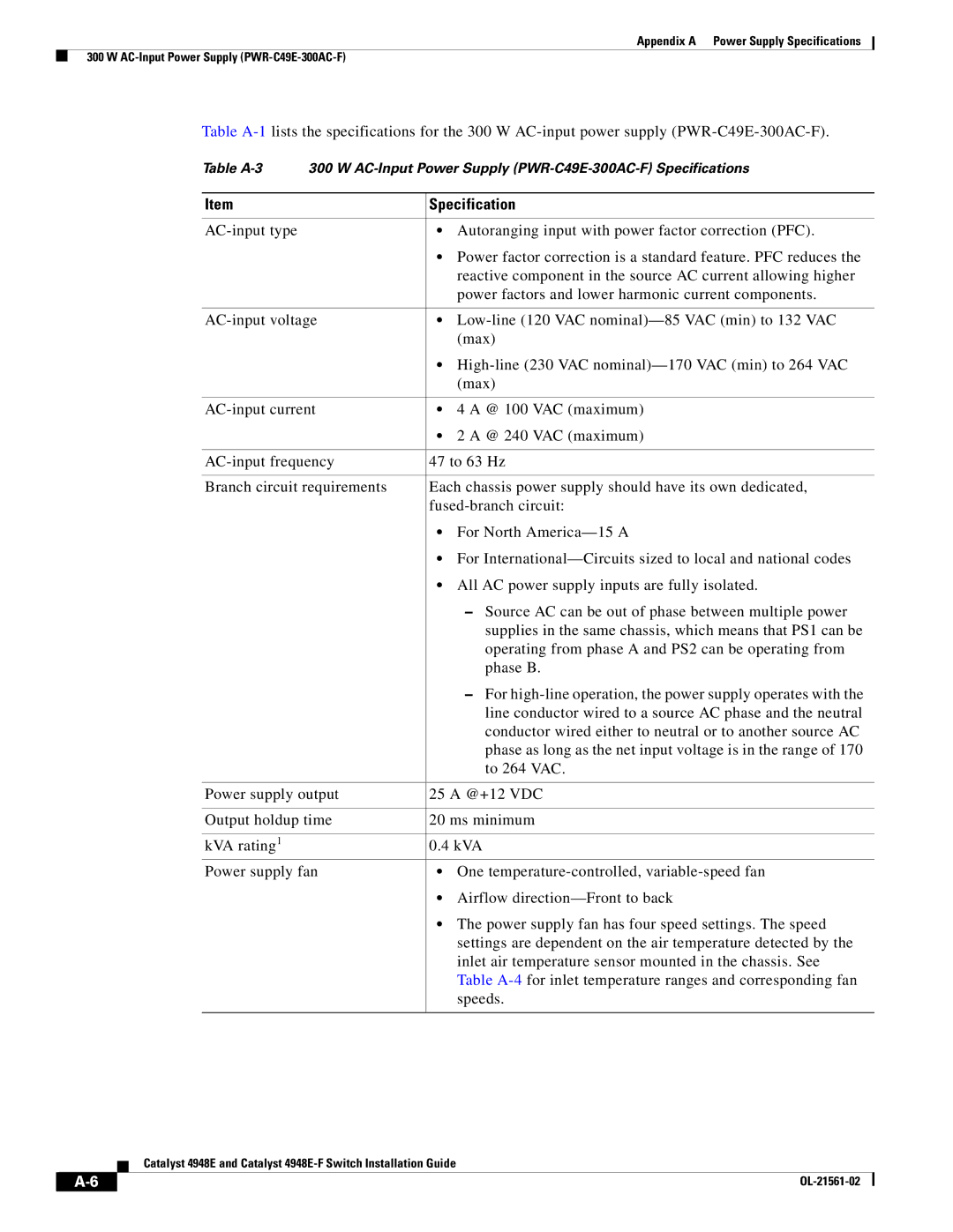
Table
Table
Item | Specification |
|
|
• Autoranging input with power factor correction (PFC). | |
| • Power factor correction is a standard feature. PFC reduces the |
| reactive component in the source AC current allowing higher |
| power factors and lower harmonic current components. |
|
|
• | |
| (max) |
| • |
| (max) |
|
|
• 4 A @ 100 VAC (maximum) | |
| • 2 A @ 240 VAC (maximum) |
|
|
47 to 63 Hz | |
|
|
Branch circuit requirements | Each chassis power supply should have its own dedicated, |
| |
| • For North |
| • For |
| • All AC power supply inputs are fully isolated. |
| – Source AC can be out of phase between multiple power |
| supplies in the same chassis, which means that PS1 can be |
| operating from phase A and PS2 can be operating from |
| phase B. |
| – For |
| line conductor wired to a source AC phase and the neutral |
| conductor wired either to neutral or to another source AC |
| phase as long as the net input voltage is in the range of 170 |
| to 264 VAC. |
|
|
Power supply output | 25 A @+12 VDC |
|
|
Output holdup time | 20 ms minimum |
|
|
kVA rating1 | 0.4 kVA |
Power supply fan | • One |
| • Airflow |
| • The power supply fan has four speed settings. The speed |
| settings are dependent on the air temperature detected by the |
| inlet air temperature sensor mounted in the chassis. See |
| Table |
| speeds. |
|
|
Catalyst 4948E and Catalyst
|
|
| |
|
|