Chapter 1 Product Overview
Features
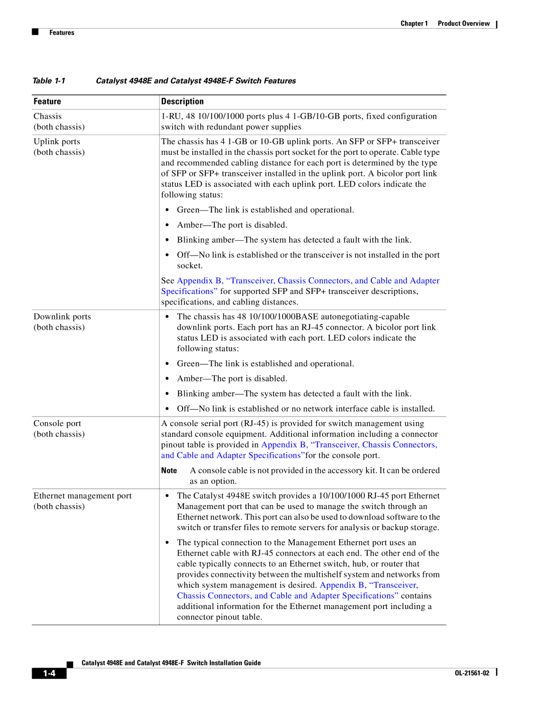
Table | Catalyst 4948E and Catalyst | |
|
|
|
Feature |
| Description |
|
|
|
Chassis |
| |
(both chassis) |
| switch with redundant power supplies |
|
|
|
Uplink ports |
| The chassis has 4 |
(both chassis) |
| must be installed in the chassis port socket for the port to operate. Cable type |
|
| and recommended cabling distance for each port is determined by the type |
|
| of SFP or SFP+ transceiver installed in the uplink port. A bicolor port link |
|
| status LED is associated with each uplink port. LED colors indicate the |
|
| following status: |
|
| • |
|
| • |
|
| • Blinking |
|
| • |
|
| socket. |
|
| See Appendix B, “Transceiver, Chassis Connectors, and Cable and Adapter |
|
| Specifications” for supported SFP and SFP+ transceiver descriptions, |
|
| specifications, and cabling distances. |
|
|
|
Downlink ports |
| • The chassis has 48 10/100/1000BASE |
(both chassis) |
| downlink ports. Each port has an |
|
| status LED is associated with each port. LED colors indicate the |
|
| following status: |
|
| • |
|
| • |
|
| • Blinking |
|
| • |
|
|
|
Console port |
| A console serial port |
(both chassis) |
| standard console equipment. Additional information including a connector |
|
| pinout table is provided in Appendix B, “Transceiver, Chassis Connectors, |
|
| and Cable and Adapter Specifications”for the console port. |
|
| Note A console cable is not provided in the accessory kit. It can be ordered |
|
| as an option. |
|
| |
Ethernet management port | • The Catalyst 4948E switch provides a 10/100/1000 | |
(both chassis) |
| Management port that can be used to manage the switch through an |
|
| Ethernet network. This port can also be used to download software to the |
|
| switch or transfer files to remote servers for analysis or backup storage. |
|
| • The typical connection to the Management Ethernet port uses an |
|
| Ethernet cable with |
|
| cable typically connects to an Ethernet switch, hub, or router that |
|
| provides connectivity between the multishelf system and networks from |
|
| which system management is desired. Appendix B, “Transceiver, |
|
| Chassis Connectors, and Cable and Adapter Specifications” contains |
|
| additional information for the Ethernet management port including a |
|
| connector pinout table. |
|
|
|
Catalyst 4948E and Catalyst
| ||
|