Chapter 1 Product Overview
Front Panel LEDs
Front Panel LEDs
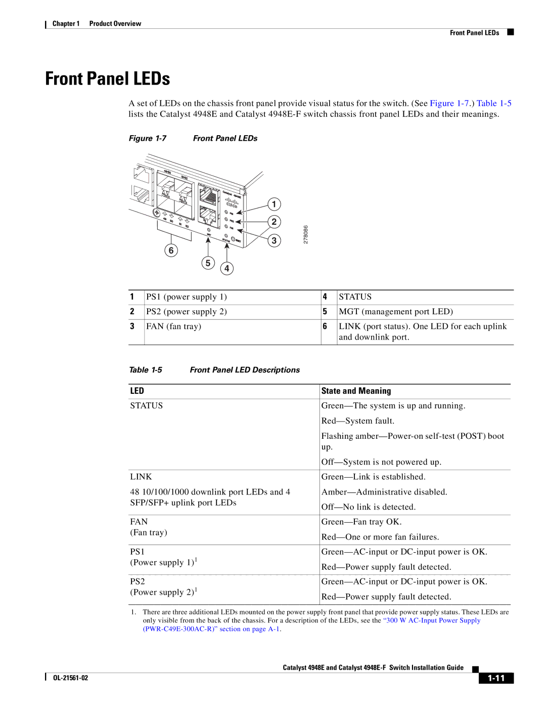
A set of LEDs on the chassis front panel provide visual status for the switch. (See Figure
Figure 1-7 Front Panel LEDs
6
5
1 |
|
2 | 278086 |
3 |
4
1 | PS1 (power supply 1) | 4 | STATUS | ||
|
|
|
|
| |
2 | PS2 (power supply 2) | 5 | MGT (management port LED) | ||
|
|
|
|
| |
3 | FAN (fan tray) | 6 | LINK (port status). One LED for each uplink | ||
|
|
|
| and downlink port. | |
|
|
|
|
|
|
Table | Front Panel LED Descriptions |
|
|
| |
|
|
|
| ||
LED |
| State and Meaning | |||
|
|
|
| ||
STATUS |
| ||||
|
|
| |||
|
|
| Flashing | ||
|
|
| up. | ||
|
|
| |||
|
|
|
| ||
LINK |
| ||||
48 10/100/1000 downlink port LEDs and 4 | |||||
SFP/SFP+ uplink port LEDs | |||||
|
|
| |||
|
|
|
| ||
FAN |
| ||||
(Fan tray) |
| ||||
|
|
| |||
|
|
|
| ||
PS1 |
| ||||
(Power supply 1)1 | |||||
|
|
| |||
|
|
|
| ||
PS2 |
| ||||
(Power supply 2)1 |
| ||||
|
|
| |||
|
|
|
|
|
|
1.There are three additional LEDs mounted on the power supply front panel that provide power supply status. These LEDs are only visible from the back of the chassis. For a description of the LEDs, see the “300 W
Catalyst 4948E and Catalyst
|
| ||
|
|