Chapter 3 Installing the Switch
Attaching the Interface Cables
Connecting to the Downlink Ports
Both chassis have 48 10/100/1000 ports. The ports configure themselves to operate at the speed of the attached devices. If the attached devices do not support autonegotiation, you can explicitly set the speed and duplex parameters.
To attach network cables to the downlink ports, follow these steps:
Step 1 Connect the
Step 2 Connect the
Step 3 Repeat Steps 1 and 2 for the remaining downlink ports.
Installing Uplink Port Transceivers and Cables
The four uplink ports on the Catalyst 4948E support either
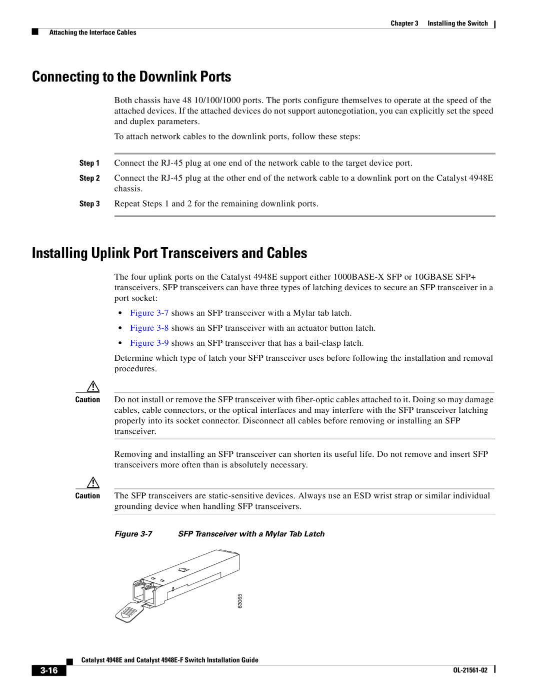
•Figure 3-7 shows an SFP transceiver with a Mylar tab latch.
•Figure 3-8 shows an SFP transceiver with an actuator button latch.
•Figure 3-9 shows an SFP transceiver that has a bail-clasp latch.
Determine which type of latch your SFP transceiver uses before following the installation and removal procedures.
Caution Do not install or remove the SFP transceiver with
Removing and installing an SFP transceiver can shorten its useful life. Do not remove and insert SFP transceivers more often than is absolutely necessary.
Caution The SFP transceivers are
Figure 3-7 SFP Transceiver with a Mylar Tab Latch
63065
| Catalyst 4948E and Catalyst |
|