Chapter 4 Removal and Replacement Procedures
Removing and Installing the
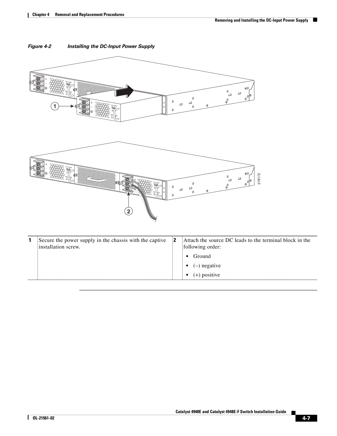
Figure 4-2 Installing the DC-Input Power Supply
+ |
|
|
| PWR - |
|
- | ||
|
| |
| 60VAC | |
| 8A | |
| INPUT | OUTPUT |
| OK | |
|
| OK |
1
+ |
|
|
| PWR - |
|
- | ||
|
| |
| 60VAC | |
| 8A | |
| INPUT | OUTPUT |
| OK | |
|
| OK |
+ |
|
|
| PWR - |
|
- | ||
|
| |
| 60VAC | |
| 8A | |
| INPUT | OUTPUT |
| OK | |
|
| OK |
+ |
|
|
| PWR - |
|
- | ||
|
| |
| 60VAC | |
| 8A | |
| INPUT | OUTPUT |
| OK | |
|
| OK |
2
278172
1 | Secure the power supply in the chassis with the captive | 2 | Attach the source DC leads to the terminal block in the | ||
| installation screw. |
| following order: | ||
|
|
|
| • | Ground |
|
|
|
| • | |
|
|
|
| • | (+) positive |
|
|
|
|
|
|
|
|
|
|
|
|
Catalyst 4948E and Catalyst
|
| ||
|
|