Chapter 3 Installing the Switch
Connecting Power to the Switch
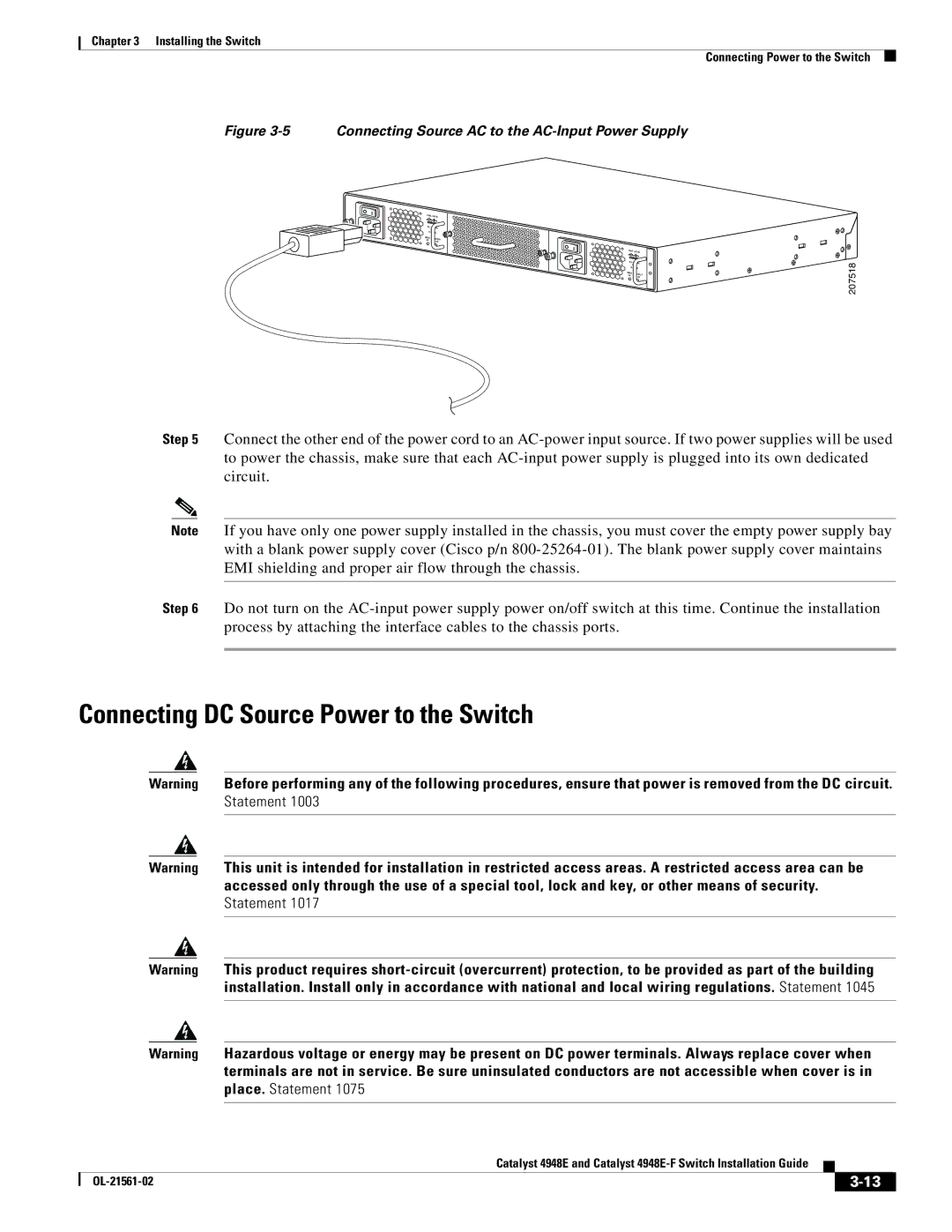
Figure 3-5 Connecting Source AC to the AC-Input Power Supply
PWR - 540 AC | |
100 - 240 VAC | |
| 7 - 3A |
50 - 60 Hz | |
INPUT | OUTPUT |
OK | |
| OK |
PWR - 540 AC | |
100 - 240 VAC | |
| 7 - 3A |
50 - 60 Hz | |
INPUT | OUTPUT |
OK | |
| OK |
207518
Step 5 Connect the other end of the power cord to an
Note If you have only one power supply installed in the chassis, you must cover the empty power supply bay with a blank power supply cover (Cisco p/n
Step 6 Do not turn on the
Connecting DC Source Power to the Switch
Warning Before performing any of the following procedures, ensure that power is removed from the DC circuit. Statement 1003
Warning This unit is intended for installation in restricted access areas. A restricted access area can be accessed only through the use of a special tool, lock and key, or other means of security. Statement 1017
Warning This product requires
Warning Hazardous voltage or energy may be present on DC power terminals. Always replace cover when terminals are not in service. Be sure uninsulated conductors are not accessible when cover is in place. Statement 1075
|
| Catalyst 4948E and Catalyst |
|
| |
|
|
| |||
|
|
|
| ||
|
|
|
| ||