Appendix B Transceiver, Chassis Connectors, and Cable and Adapter Specifications
Console Port
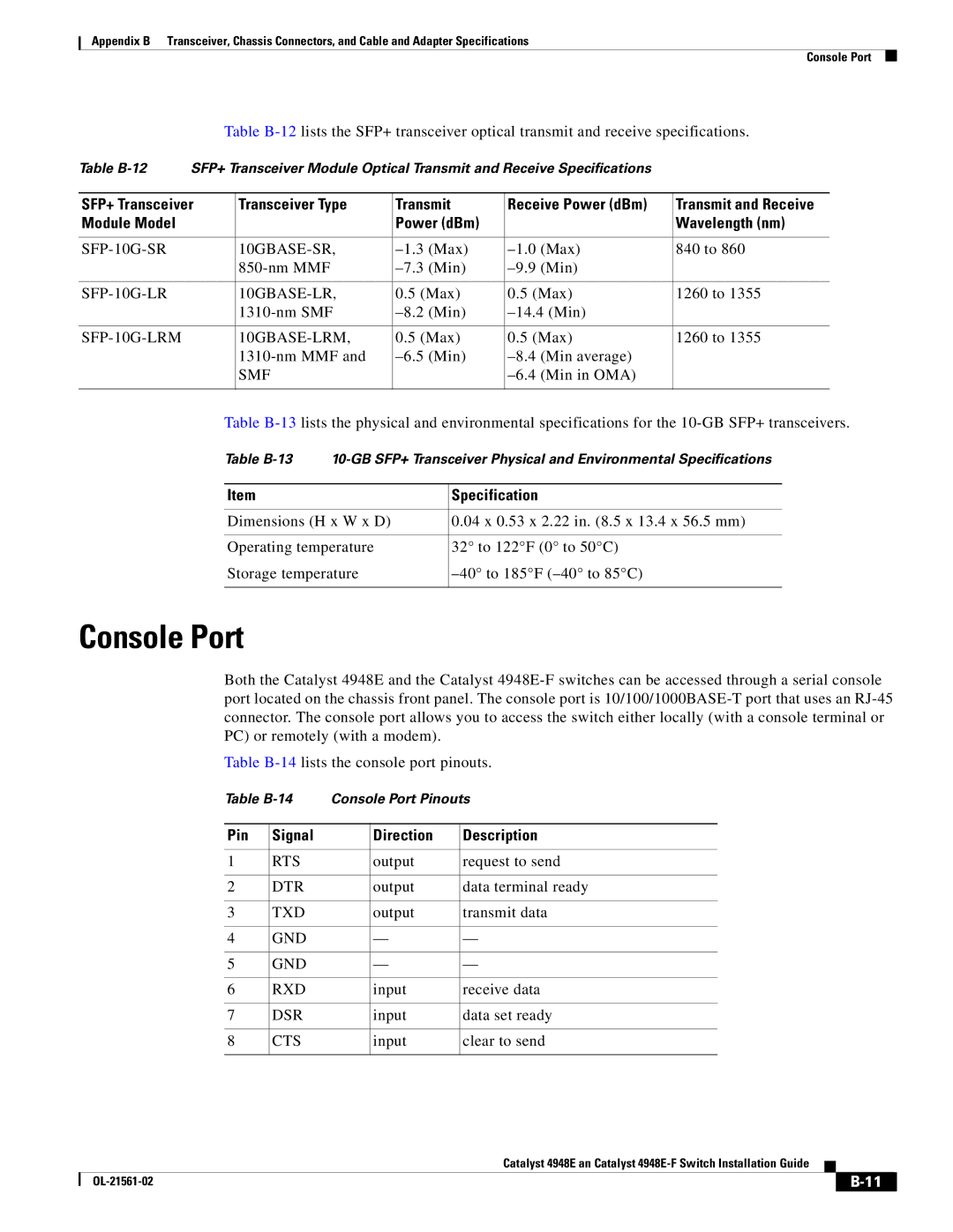
Table
Table | SFP+ Transceiver Module Optical Transmit and Receive Specifications |
| |||
|
|
|
|
| |
SFP+ Transceiver | Transceiver Type | Transmit | Receive Power (dBm) | Transmit and Receive | |
Module Model |
|
| Power (dBm) |
| Wavelength (nm) |
|
|
|
|
|
|
| 840 to 860 | ||||
|
|
| |||
|
|
|
|
|
|
| 0.5 (Max) | 0.5 (Max) | 1260 to 1355 | ||
|
|
| |||
|
|
|
|
|
|
| 0.5 (Max) | 0.5 (Max) | 1260 to 1355 | ||
|
|
| |||
|
| SMF |
|
| |
|
|
|
|
|
|
Table
Table
Item | Specification |
|
|
Dimensions (H x W x D) | 0.04 x 0.53 x 2.22 in. (8.5 x 13.4 x 56.5 mm) |
|
|
Operating temperature | 32° to 122°F (0° to 50°C) |
Storage temperature | |
|
|
Console Port
Both the Catalyst 4948E and the Catalyst
Table
Table | Console Port Pinouts | |||
|
|
|
|
|
Pin | Signal |
| Direction | Description |
|
|
|
|
|
1 | RTS |
| output | request to send |
|
|
|
|
|
2 | DTR |
| output | data terminal ready |
|
|
|
|
|
3 | TXD |
| output | transmit data |
|
|
|
|
|
4 | GND |
| — | — |
|
|
|
|
|
5 | GND |
| — | — |
|
|
|
|
|
6 | RXD |
| input | receive data |
|
|
|
|
|
7 | DSR |
| input | data set ready |
|
|
|
|
|
8 | CTS |
| input | clear to send |
|
|
|
|
|
|
| Catalyst 4948E an Catalyst |
|
|
|
|
|
| |||
|
|
|
| ||
|
|
|
|