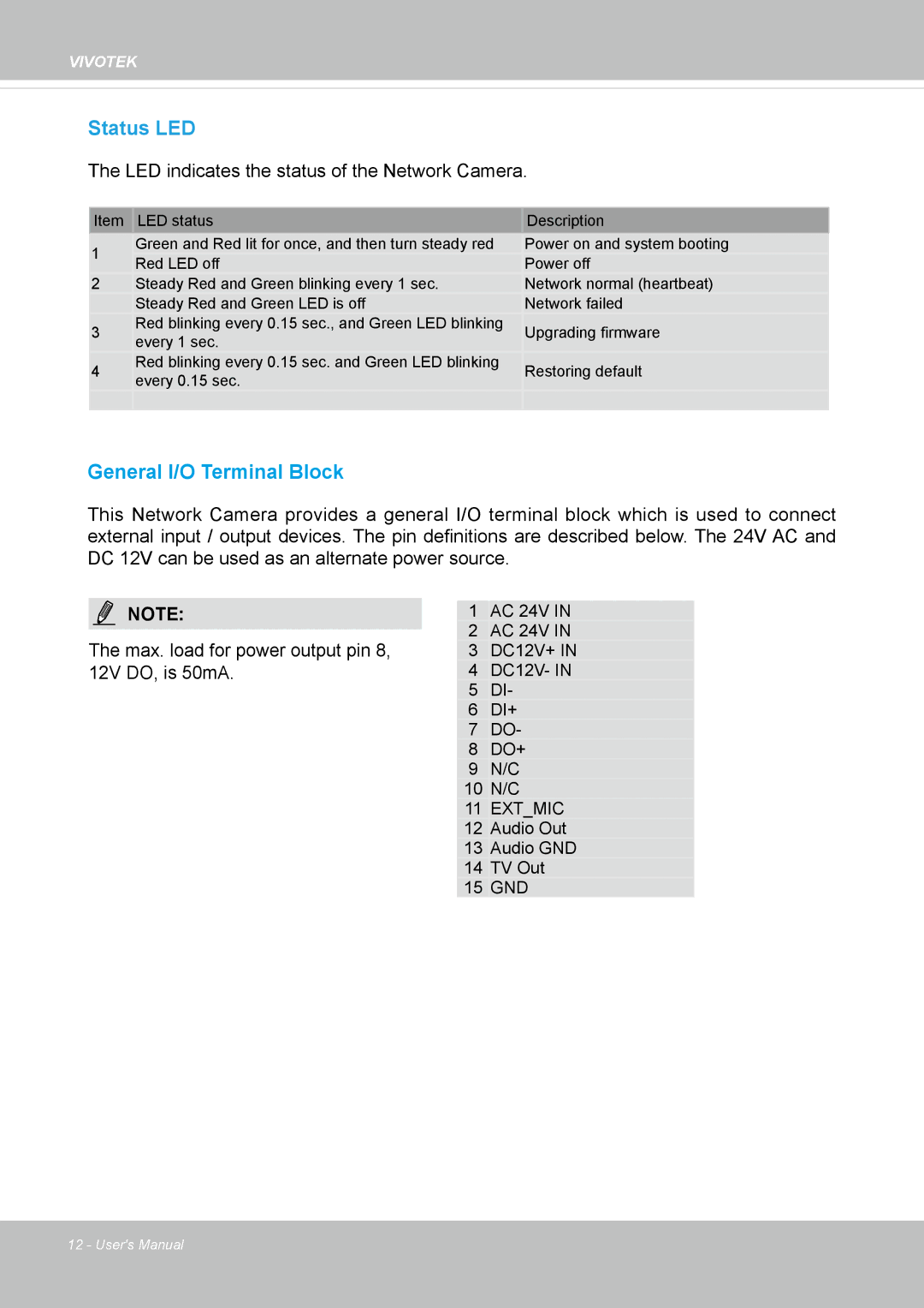
IP8355EH specifications
The Vivotek IP8355EH is a sophisticated IP camera designed to meet the demands of various surveillance applications. With its blend of advanced technologies and robust features, this camera is ideal for monitoring both indoor and outdoor environments.One of the standout features of the IP8355EH is its 2-Megapixel resolution, which ensures clear, high-definition video captures. This clarity is essential for detailed monitoring, whether for security purposes or general surveillance. The camera utilizes a 1/2.7" progressive scan CMOS sensor, allowing for improved performance in low-light conditions, delivering quality images even in challenging lighting.
Built for resilience, the Vivotek IP8355EH boasts an IP66 weatherproof rating, making it suitable for outdoor usage where exposure to harsh weather elements is a concern. Additionally, it comes equipped with an IK10-rated vandal-proof housing, providing an added layer of protection against tampering or physical damage.
The camera features wide dynamic range (WDR) technology, which enhances visibility in high-contrast scenes. This capability is crucial in environments where backlighting may present challenges, enabling clear images of both bright and dark areas within a single frame.
With the Smart Stream II technology, the camera efficiently optimizes bandwidth usage without compromising image quality. This feature adjusts the image quality according to the monitored area and the level of detail needed, resulting in significant savings on storage capacity.
The IP8355EH is equipped with a built-in Infrared (IR) LED, providing night vision capabilities up to 30 meters. This allows continuous monitoring even in complete darkness, ensuring round-the-clock surveillance for enhanced security.
Networking capabilities are robust, with support for both Ethernet and Wi-Fi, enabling flexible installation options. Moreover, it supports Power over Ethernet (PoE), simplifying the deployment process by allowing power and data to be transmitted over a single cable.
Additionally, the camera is compliant with the ONVIF standard, ensuring compatibility with various video management systems. This interoperability is key for users seeking to integrate the IP8355EH into existing surveillance setups.
Overall, Vivotek's IP8355EH is a feature-rich, reliable outdoor IP camera that stands out in the competitive landscape of surveillance technology. Its combination of high-resolution imaging, durable design, low-light performance, and user-friendly features makes it an excellent choice for ensuring the safety and security of any environment.

