Descriptions and Functions
� | � | � | � |
� | � | � |
![]()
![]()
![]()
![]()
![]()
![]()
![]()
![]()
![]()
![]()
![]()
![]()
![]()
![]()
![]()
![]() �
�
�
� |
Front Panel
�� �� | �� |
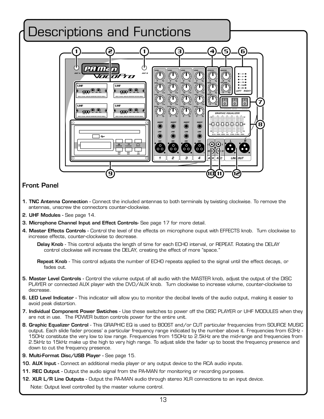
1.TNC Antenna Connection - Connect the included antennas to both terminals by twisting clockwise. To remove the antennas, unscrew the connectors
2.UHF Modules - See page 14.
3.Microphone Channel Input and Effect Controls- See page 17 for more detail.
4.Master Effects Controls - Control the level of the effects on microphone ouput with EFFECTS knob. Turn clockwise to increase effects,
Delay Knob - This control adjusts the length of time for each ECHO interval, or REPEAT. Rotating the DELAY control clockwise will increase the DELAY, creating the effect of more “space.”
Repeat Knob - This control adjusts the number of ECHO repeats applied to the signal until the effect decays, or fades out.
5.Master Level Controls - Control the volume output of all audio with the MASTER knob, adjust the output of the DISC PLAYER or connected AUX player with the DVD/AUX knob. Turn clockwise to increase volume,
6.LED Level Indicator - This indicator will allow you to monitor the decibal levels of the audio output, making it easier to avoid peak distortion.
7.Individual Component Power Swtiches - Use these switches to power off the DISC PLAYER or UHF MODULES when they are not in use. The POWER button controls power for the entire unit.
8.Graphic Equalizer Control - This GRAPHIC EQ is used to BOOST and/or CUT particular frequencies from SOURCE MUSIC output. Each slide fader process’ a particular frequency range indicated by the number above it. Frequencies from 63Hz - 150Hz constitute the very low to low range. Frequencies from 150Hz to 2.5kHz are the
9.
10.AUX Input - Connect an additional media player or any output device to the RCA audio inputs.
11.REC Output - Output the audio signal from the
12.XLR L/R Line Outputs - Output the
Note: Output level controlled by the master volume control.
13
