
UHF-5805 specifications
The VocoPro UHF-5805 is a high-performance wireless microphone system designed for professional and semi-professional use. Ideal for karaoke enthusiasts, public speaking, or live performances, this system stands out with its robust features and reliable performance.One of the most notable characteristics of the UHF-5805 is its UHF technology. Unlike VHF systems, UHF provides a wider frequency range, allowing for better sound quality and less susceptibility to interference. This feature is particularly beneficial in crowded environments, such as concert venues or conferences, where multiple wireless devices might be in use simultaneously. The UHF-5805 operates on a frequency range from 550 to 590 MHz, ensuring clear transmission across various settings.
The system comes with two handheld microphones, which utilize dynamic capsules for superior sound quality. These microphones offer a wide frequency response, allowing vocalists to express their full range without distortion. Additionally, the microphones are designed with ergonomic grips for comfortable use during extended performances, making them ideal for any event.
One of the standout technologies in the UHF-5805 is the Automatic Frequency Scan. This feature assists users in finding the clearest frequency available to avoid interference from other wireless sources. In addition, the system comes equipped with a digital display that provides real-time information about frequency, signal strength, and battery life. This allows users to monitor their equipment easily, making adjustments on the fly if necessary.
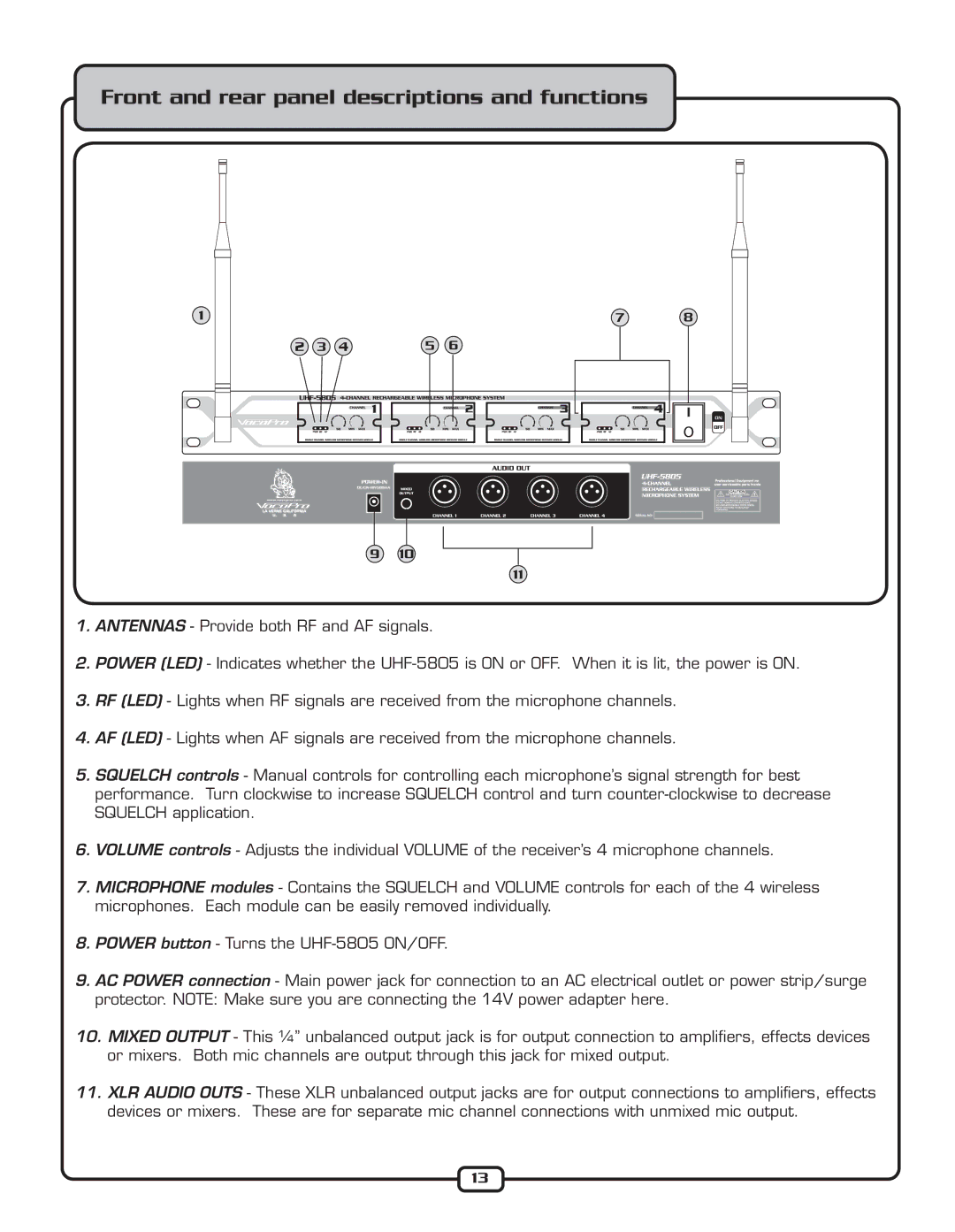
The UHF-5805 is also equipped with a range of connectivity options, including XLR and 1/4” outputs. This versatility makes it compatible with various audio equipment, from PA systems to mixers and amplifiers. With a range of up to 300 feet, users can move freely across the stage or event space without being tethered to their sound source.
Furthermore, the VocoPro UHF-5805 features a rechargeable battery option, enhancing its portability and convenience. Users can confidently engage in lengthy performances without the worry of changing batteries unexpectedly.
Overall, the VocoPro UHF-5805 is a sophisticated wireless microphone system that combines cutting-edge technology with user-friendly features. With its superior sound quality, reliable performance, and versatile connectivity, it is an excellent choice for anyone looking to enhance their audio experience in live settings.