Brian May Special Signal Path Flowchart
9V BATTERY SIMULATOR
TREBLE GAIN
T
SBOOSTER
| 9V BATTERY SIMULATOR |
| T | HEADPHONE |
|
| R | AND | |
|
|
| ||
|
|
| S | RECORDING |
| OUTPUT |
| SPEAKER SYSTEM | OUTPUT |
| TONE |
| ||
BOOSTER ONLY | TRANSFORMER | EMULATION |
| |
SIMULATION |
|
|
| |
OUTPUT JACK |
|
|
|
|
T |
|
|
|
|
R |
|
| VOLUME |
|
S | PREAMP |
|
| T |
|
|
|
| |
| & DRIVER STAGE |
|
| S |
|
|
|
|
| 10 Watt | EXTERNAL |
| POWER AMP | |
| LOUDSPEAKER | |
GAIN SWITCH |
| |
| OUTPUT |
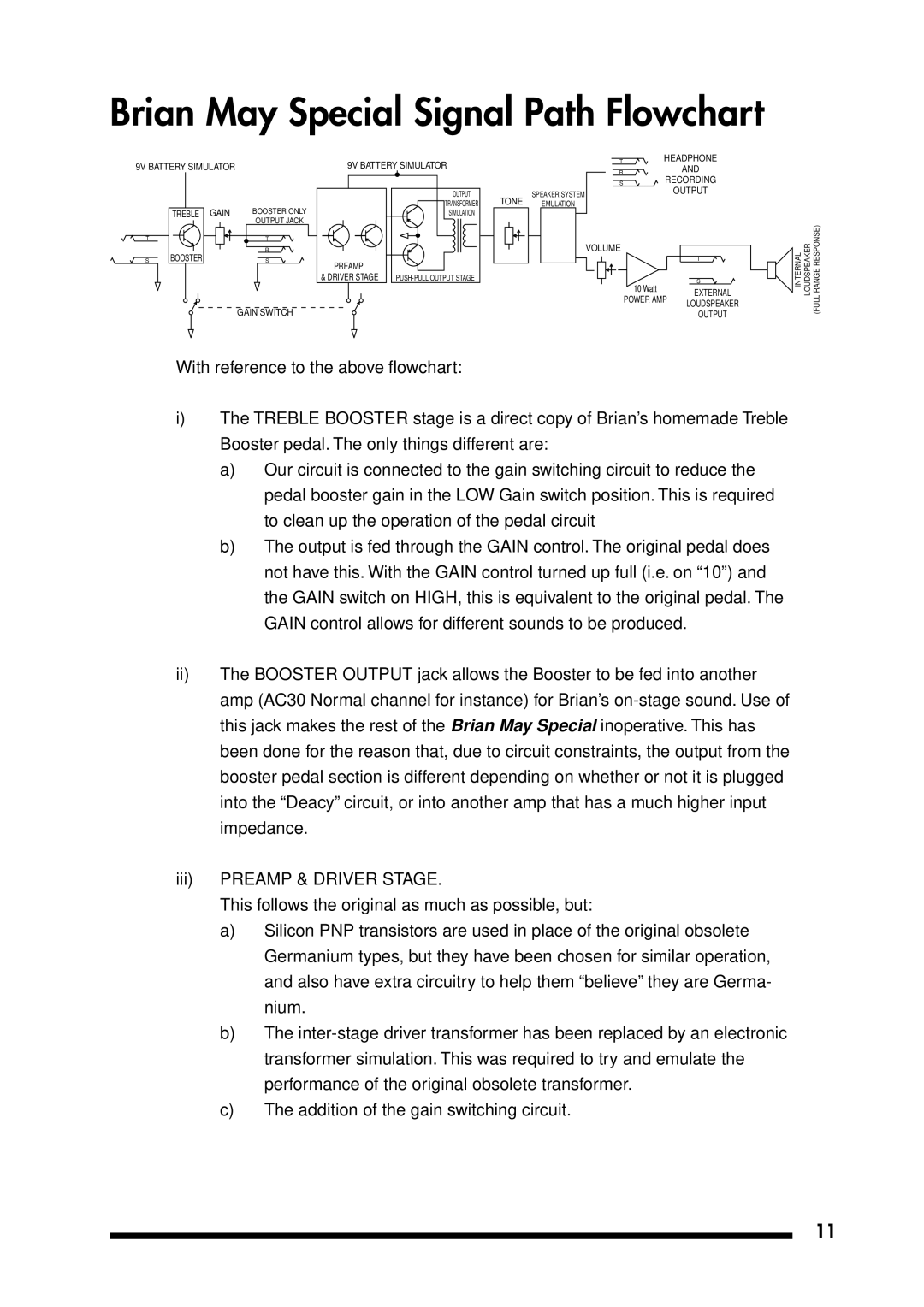
With reference to the above flowchart:
i)The TREBLE BOOSTER stage is a direct copy of Brian’s homemade Treble Booster pedal. The only things different are:
a)Our circuit is connected to the gain switching circuit to reduce the pedal booster gain in the LOW Gain switch position. This is required to clean up the operation of the pedal circuit
b)The output is fed through the GAIN control. The original pedal does not have this. With the GAIN control turned up full (i.e. on “10”) and the GAIN switch on HIGH, this is equivalent to the original pedal. The GAIN control allows for different sounds to be produced.
ii)The BOOSTER OUTPUT jack allows the Booster to be fed into another amp (AC30 Normal channel for instance) for Brian’s
iii)PREAMP & DRIVER STAGE.
This follows the original as much as possible, but:
a)Silicon PNP transistors are used in place of the original obsolete Germanium types, but they have been chosen for similar operation, and also have extra circuitry to help them “believe” they are Germa- nium.
b)The
c)The addition of the gain switching circuit.
11