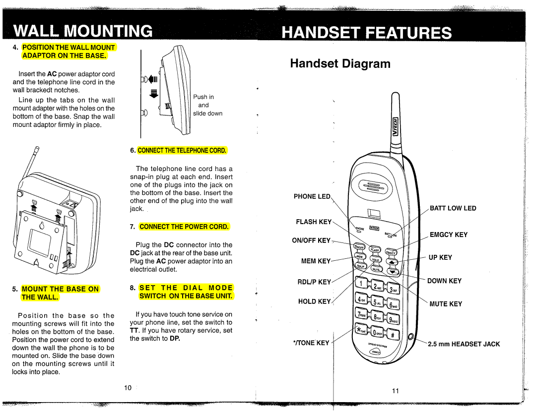
VT 1980, VT-1981 specifications
The VTech VT-1980 and VT-1981 are significant entries in the realm of educational toys, part of VTech's pioneering series of early learning devices aimed at nurturing young minds through interactive play. Launched in the early 1980s, these models stand out for their innovative use of technology and their engaging user experience.The VT-1980, in particular, showcased a combination of fun and educational content designed to assist children in their early developmental stages. With a vibrant, colorful design that appealed to children, it featured a straightforward interface, ensuring that users could navigate the device without frustration. The device primarily functioned as an interactive learning tool, encouraging kids to engage with letters, numbers, and basic words.
One of the notable features of the VT-1980 was its multiple game modes, which provided an entertaining way to learn foundational skills. This included word recognition and simple math exercises, allowing children to practice through play. Its audio capabilities were also a highlight, with pleasant sound effects and encouraging voice prompts that motivated children to continue exploring.
Transitioning to the VT-1981, VTech made several enhancements upon its predecessor. The VT-1981 introduced more advanced learning modules, featuring an expanded library of games and activities that covered a broader range of educational topics. This model emphasized interactivity even further, incorporating touch-sensitive keys that responded to children’s inputs more effectively, enhancing their engagement with the device.
Both models utilized durable construction, ensuring the toys could withstand the rigors of play while remaining safe for young users. The technology was designed with longevity in mind, engaging children not just once but encouraging repeated use and continued learning over time.
Furthermore, VTech's commitment to providing educational content resonated across both models. They took significant steps to ensure that parents could trust the devices to offer quality learning experiences, highlighting the brand’s dedication to early childhood education.
In conclusion, the VTech VT-1980 and VT-1981 are exemplary representations of how technology can merge with play to create enriching educational experiences for young children. Their innovative features, combined with VTech's relentless pursuit of educational value, solidified their position as beloved tools in early learning, marking an important chapter in the evolution of educational toys.

