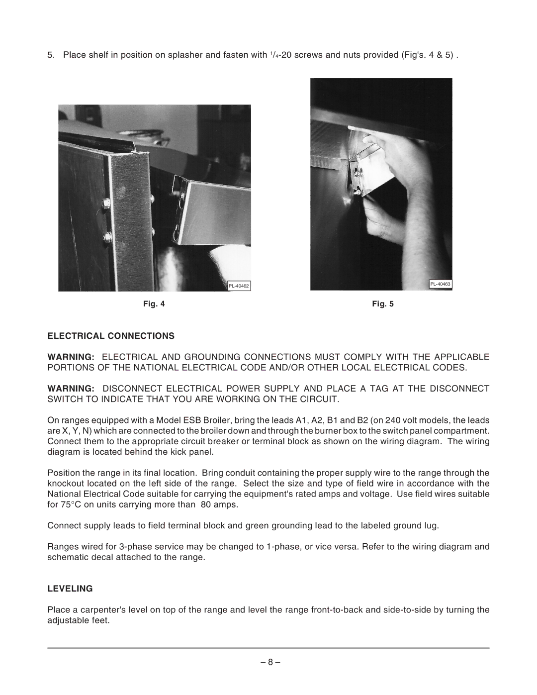
5. Place shelf in position on splasher and fasten with
Fig. 4
Fig. 5
ELECTRICAL CONNECTIONS
WARNING: ELECTRICAL AND GROUNDING CONNECTIONS MUST COMPLY WITH THE APPLICABLE PORTIONS OF THE NATIONAL ELECTRICAL CODE AND/OR OTHER LOCAL ELECTRICAL CODES.
WARNING: DISCONNECT ELECTRICAL POWER SUPPLY AND PLACE A TAG AT THE DISCONNECT SWITCH TO INDICATE THAT YOU ARE WORKING ON THE CIRCUIT.
On ranges equipped with a Model ESB Broiler, bring the leads A1, A2, B1 and B2 (on 240 volt models, the leads are X, Y, N) which are connected to the broiler down and through the burner box to the switch panel compartment. Connect them to the appropriate circuit breaker or terminal block as shown on the wiring diagram. The wiring diagram is located behind the kick panel.
Position the range in its final location. Bring conduit containing the proper supply wire to the range through the knockout located on the left side of the range. Select the size and type of field wire in accordance with the National Electrical Code suitable for carrying the equipment's rated amps and voltage. Use field wires suitable for 75°C on units carrying more than 80 amps.
Connect supply leads to field terminal block and green grounding lead to the labeled ground lug.
Ranges wired for
LEVELING
Place a carpenter's level on top of the range and level the range
– 8 –