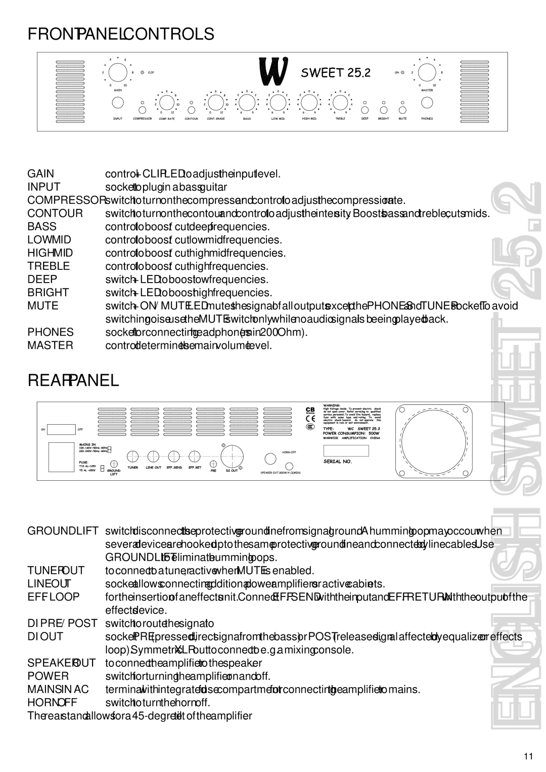
FRONT PANEL CONTROLS

GAIN

control + CLIP LED to adjust the input level.


INPUT

socket to plug in a bass guitar.


COMPRESSOR

switch to turn on the compressor and control to adjust the compression rate.


CONTOUR

switch to turn on the contour and control to adjust the intensity. Boosts bass and treble, cuts mids.

BASS

control to boost / cut deep frequencies.

25.2

LOW MID

control to boost / cut low mid frequencies.

HIGH MID

control to boost / cut high mid frequencies.

TREBLE

control to boost / cut high frequencies.

DEEP

switch + LED to boost low frequencies.

BRIGHT

switch + LED to boost high frequencies.

MUTE


switch + ON / MUTE LED mutes the signal of all outputs except the PHONES and TUNER socket. To avoid

PHONES

switching noise use the MUTE switch only while no audio signal is beeing played back.


socket for connecting headphones (min 200 Ohm).


MASTER

control determines the main volume level.


REAR PANEL


SWEET


GROUNDLIFT


switch disconnects the protective ground line from signal ground. A humming loop may occour when


several devices are hooked up to the same protective ground line and connected by line cables. Use


TUNER OUT

GROUNDLIFT to eliminate humming loops.


to connect to a tuner, active when MUTE is enabled.


LINE OUT

socket allows connecting additional power amplifiers or active cabinets.


EFF. LOOP

for the insertion of an effects unit. Connect EFF. SEND with the input and EFF. RETURN with the output of the


DI PRE / POST

effects device.


switch to route the signal to


DI OUT

socket PRE (pressed, direct signal from the bass) or POST (released, signal affected by equalizer or effects

SPEAKER OUT

loop). Symmetric XLR out to connect to e.g. a mixing console.


to connect the amplifier to the speaker.


POWER

switch for turning the amplifier on and off.


MAINS IN AC

terminal with integrated fuse compartment for connecting the amplifier to mains.


HORN OFF

switch to turn the horn off.


The rear stand allows for a 45-degree tilt of the amplifier.


ENGLISH


11

Page 7
Image 7
Warwick 25.2, 15.3 owner manual

15.3, 25.2 specifications

Warwick 25.2,15.3 is a versatile and robust solution designed for diverse applications, notably in the fields of engineering, manufacturing, and construction. This duality in its naming convention signifies the dimensions and capabilities that make it a preferred choice for professionals seeking reliability and performance.

The Warwick 25.2,15.3 is characterized by its exceptional strength and durability, crafted from high-grade materials that ensure a long lifespan under demanding conditions. Its construction incorporates advanced engineering techniques that enhance its load-bearing capacity, making it ideal for heavy-duty use. This model is particularly noted for its resistance to wear and tear, ensuring that it maintains its integrity even in the most challenging environments.

One of the main features of the Warwick 25.2,15.3 is its adaptability. It is designed to cater to various applications, allowing for seamless integration into existing systems. This flexibility is a hallmark of its design, making it suitable for industries ranging from automotive to aerospace, where precision and reliability are paramount.

Technologically, the Warwick 25.2,15.3 leverages cutting-edge innovations. The incorporation of smart sensors allows for real-time monitoring, providing users with data that can optimize performance and enhance safety. This feature not only helps in identifying potential issues before they escalate but also ensures that operations run smoothly, minimizing downtime.

Moreover, the Warwick model is engineered with user-friendliness in mind. The intuitive controls and setup process make it accessible for operators of all skill levels. This ease of use significantly reduces the learning curve and increases productivity, ensuring that teams can operate effectively from day one.

Energy efficiency is another critical characteristic of the Warwick 25.2,15.3. With a focus on sustainable operations, this model integrates energy-saving technologies that reduce consumption without compromising on performance. This not only benefits the environment but also translates into cost savings for businesses.

In summary, the Warwick 25.2,15.3 stands out due to its robust construction, adaptability, advanced technology features, user-friendly operation, and energy efficiency. These elements combine to make it an excellent choice for professionals who demand reliability and efficiency in their work. Whether for new projects or upgrades of existing systems, this model is designed to meet the rigorous standards of today’s dynamic industries.