156CHAPTER 16: MULTICAST CONFIGURATION GUIDE
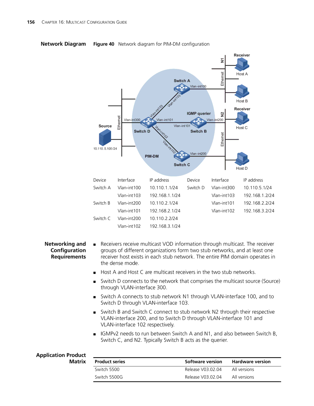
Network Diagram Figure 40 Network diagram for PIM-DM configuration
|
|
|
|
|
|
|
|
|
|
|
|
| Receiver | |
|
|
|
|
|
|
|
|
|
|
|
|
| N1 |
|
|
|
|
|
|
|
|
|
|
|
|
|
| Ethernet | Host A |
|
|
|
|
|
|
|
|
|
| Switch A |
|
| ||
|
|
|
|
|
|
|
|
|
|
|
|
| ||
|
|
|
|
|
|
|
|
|
|
|
|
|
| |
|
|
|
|
|
|
|
|
|
| 3 |
|
|
|
|
|
|
|
|
|
|
|
|
|
| t10 |
|
|
| Host B |
|
|
|
|
|
|
|
|
|
| in |
|
|
| |
|
|
|
|
|
|
|
|
| - |
|
|
| ||
|
|
|
|
|
|
|
|
| n |
|
|
|
|
|
|
|
|
|
|
|
|
| 3 | la |
|
|
|
|
|
|
|
|
|
|
| t10 | V |
|
|
| Receiver | |||
|
|
|
|
|
|
|
|
|
|
| ||||
|
|
|
|
|
| in |
|
|
|
| IGMP querier | N2 |
| |
|
|
|
|
| - |
|
|
|
|
| ||||
| Ethernet |
|
| Vl | an |
|
|
|
|
|
| |||
|
|
|
|
|
|
|
|
|
|
|
| |||
|
|
| Vlan |
|
| |||||||||
|
|
|
|
|
| |||||||||
Source |
|
|
| V |
|
|
|
|
| Host C | ||||
|
|
|
|
| la |
|
|
|
|
|
|
| ||
| Switch D |
|
| n |
|
|
| Switch B |
|
| ||||
|
|
|
|
| - |
|
|
|
|
| ||||
|
|
|
|
| i |
|
|
| Ethernet |
| ||||
|
|
|
|
| nt |
|
|
|
| |||||
|
|
|
|
|
|
|
| 1 |
|
|
|
|
| |
|
|
|
|
|
|
|
| 0 |
|
|
|
|
| |
|
|
|
|
|
|
|
| 2 |
|
|
|
|
| |
|
|
|
|
|
|
|
| V |
|
|
|
|
| |
|
|
|
|
|
|
|
| l |
|
|
|
|
| |
|
|
|
|
|
|
|
| a |
|
|
|
|
| |
|
|
|
|
|
|
|
| n |
|
|
|
| ||
|
|
|
|
|
|
|
| - |
|
|
|
| ||
|
|
|
|
|
|
|
|
| i |
|
|
|
|
|
10.110.5.100/24 |
|
|
|
|
|
|
|
| n |
|
|
|
|
|
|
|
|
|
|
|
|
| t |
|
|
|
|
| |
|
|
|
|
|
|
|
| 1 |
|
|
|
|
| |
|
|
|
|
|
|
|
|
| 0 |
|
|
|
| |
|
|
|
|
| 2 |
|
|
| ||||||
|
|
|
|
|
|
|
|
|
| |||||
|
|
|
|
|
|
|
|
|
|
| ||||
|
|
|
|
|
|
|
|
|
| Switch C |
|
| Host D | |
|
|
|
|
|
|
|
|
|
|
|
|
|
| |
Device | Interface | IP address |
| Device |
| Interface | IP address | |||||||
Switch A | 10.110.1.1/24 | Switch D |
| 10.110.5.1/24 | ||||||||||
| 192.168.1.1/24 |
|
| 192.168.1.2/24 | ||||||||||
Switch B | 10.110.2.1/24 |
|
| 192.168.2.2/24 | ||||||||||
| 192.168.2.1/24 |
|
| 192.168.3.2/24 | ||||||||||
Switch C | 10.110.2.2/24 |
|
|
|
| |||||||||
| 192.168.3.1/24 |
|
|
|
| |||||||||
Networking and | ■ Receivers receive multicast VOD information through multicast. The receiver |
Configuration | groups of different organizations form two stub networks, and at least one |
Requirements | receiver host exists in each stub network. The entire PIM domain operates in |
| the dense mode. |
■Host A and Host C are multicast receivers in the two stub networks.
■Switch D connects to the network that comprises the multicast source (Source) through
■Switch A connects to stub network N1 through
■Switch B and Switch C connect to stub network N2 through their respective
■IGMPv2 needs to run between Switch A and N1, and also between Switch B, Switch C, and N2. Typically Switch B acts as the querier.
Application Product
Matrix | Product series | Software version | Hardware version |
| Switch 5500 | Release V03.02.04 | All versions |
| Switch 5500G | Release V03.02.04 | All versions |
|
|
|
|