138CHAPTER 16: MULTICAST CONFIGURATION GUIDE
Configuring IGMP
Snooping Only
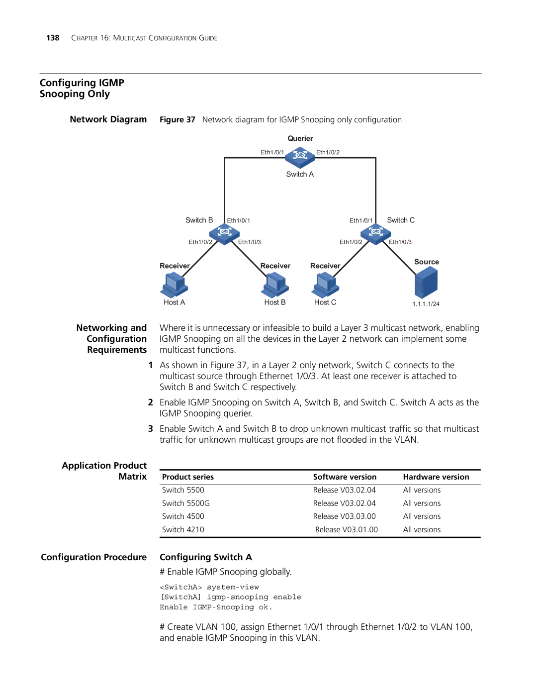
Network Diagram Figure 37 Network diagram for IGMP Snooping only configuration
Querier
Eth1/0/1 Eth1/0/2
Switch A
Switch B
Eth1/0/1 | Eth1/0/1 |
Switch C
Eth1/0/2 | Eth1/0/3 | Eth1/0/2 | Eth1/0/3 |
Receiver | Receiver | Receiver | Source |
| |||
Host A | Host B | Host C | 1.1.1.1/24 |
Networking and Where it is unnecessary or infeasible to build a Layer 3 multicast network, enabling Configuration IGMP Snooping on all the devices in the Layer 2 network can implement some Requirements multicast functions.
1As shown in Figure 37, in a Layer 2 only network, Switch C connects to the multicast source through Ethernet 1/0/3. At least one receiver is attached to Switch B and Switch C respectively.
2Enable IGMP Snooping on Switch A, Switch B, and Switch C. Switch A acts as the IGMP Snooping querier.
3Enable Switch A and Switch B to drop unknown multicast traffic so that multicast traffic for unknown multicast groups are not flooded in the VLAN.
Application Product
Matrix | Product series | Software version | Hardware version |
| Switch 5500 | Release V03.02.04 | All versions |
| Switch 5500G | Release V03.02.04 | All versions |
| Switch 4500 | Release V03.03.00 | All versions |
| Switch 4210 | Release V03.01.00 | All versions |
|
|
|
|
Configuration Procedure | Configuring Switch A |
|
|
# Enable IGMP Snooping globally.
<SwitchA>
[SwitchA]
Enable
#Create VLAN 100, assign Ethernet 1/0/1 through Ethernet 1/0/2 to VLAN 100, and enable IGMP Snooping in this VLAN.