72CHAPTER 13: AUTO DETECT CONFIGURATION GUIDE
Auto Detect | You can implement VLAN interface backup through auto detect. When data can | ||||||||
Implementation in | be transmitted through two VLAN interfaces on the switch to the same | ||||||||
VLAN Interface | destination, configure one of the VLAN interfaces as the active interface and the | ||||||||
Backup | other as the standby interface. Through the auto detect function, the standby | ||||||||
| interface is enabled automatically when the active fails, so as to ensure the data | ||||||||
| transmission: |
|
|
|
|
| |||
| ■ In normal situations (that is, when the detected group is reachable), the | ||||||||
| standby VLAN interface is down and packets are sent to the destination | ||||||||
| through the active VLAN interface. |
|
| ||||||
| ■ When the communication between the active VLAN interface and the | ||||||||
| destination fails (that is, the detected group is unreachable), the system | ||||||||
| enables the backup VLAN interface. |
|
| ||||||
| ■ When the communication between the active VLAN interface and the | ||||||||
| destination resumes, the system shuts down the standby VLAN interface again. | ||||||||
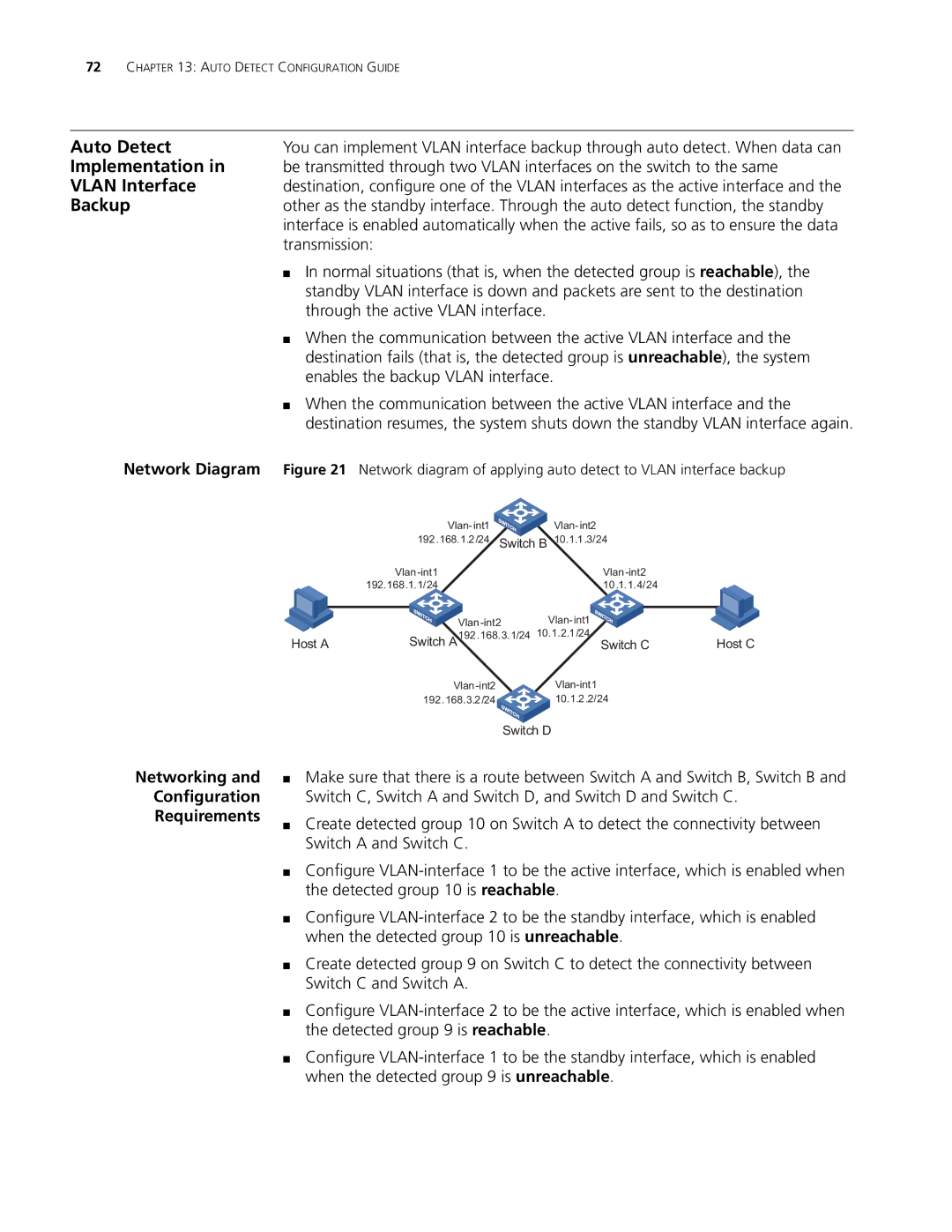
Network Diagram | Figure 21 Network diagram of applying auto detect to VLAN interface backup | ||||||||
|
|
|
| Vlan- int1 | Vlan- int2 |
|
| ||
|
|
| 192.168.1.2 /24 Switch B 10.1.1 .3/24 |
|
| ||||
|
|
|
| Vlan |
|
| |||
|
|
| 192.168.1.1/24 |
| 10 .1.1.4/24 |
|
| ||
|
|
|
|
|
|
|
|
|
|
|
|
|
|
| Vlan- int1 |
|
| ||
| Host A | Switch A | 192.168.3.1/24 | 10.1.2.1/24 |
| Host C | |||
|
| Switch C | |||||||
|
|
|
|
|
| ||||
|
|
| 192.168.3.2 /24 | 10.1.2 .2/24 |
|
|
| ||
Switch D
Networking and
Configuration
Requirements
■Make sure that there is a route between Switch A and Switch B, Switch B and Switch C, Switch A and Switch D, and Switch D and Switch C.
■Create detected group 10 on Switch A to detect the connectivity between Switch A and Switch C.
■Configure
■Configure
■Create detected group 9 on Switch C to detect the connectivity between Switch C and Switch A.
■Configure
■Configure