324CHAPTER 35:
■Configure Switch B
#
vlan 1040
#
interface Ethernet1/0/21 port access vlan 1040 undo ntdp enable
stp disable
#
interface Ethernet1/0/22 port
port trunk permit vlan 1 1040
Precautions ■ Do not configure VLAN 1040 as the default VLAN of Ethernet 1/0/12 of Switch A or Ethernet 1/0/22 of Switch B. Otherwise, the outer tag will be removed before a packet is transmitted.
■This example assumes that Ethernet 1/0/11 of Switch A and Ethernet 1/0/21 of Switch B are both access ports. If the two ports are trunk or hybrid ports, specify the default VLAN of the two ports as VLAN 1040, and configure the ports to send untagged packets of VLAN 1040. For detailed information, refer to “Port Basic Configuration” in the Configuration Guide for your product.
Configuring BPDU | With the BPDU tunnel feature, a switch can transmit Layer 2 protocol packets | ||||
Tunnel | (NDP packets in this example) along tunnels established on the public network, | ||||
| implementing unified network calculation and maintenance for the private | ||||
| networks connected through the public network. | ||||
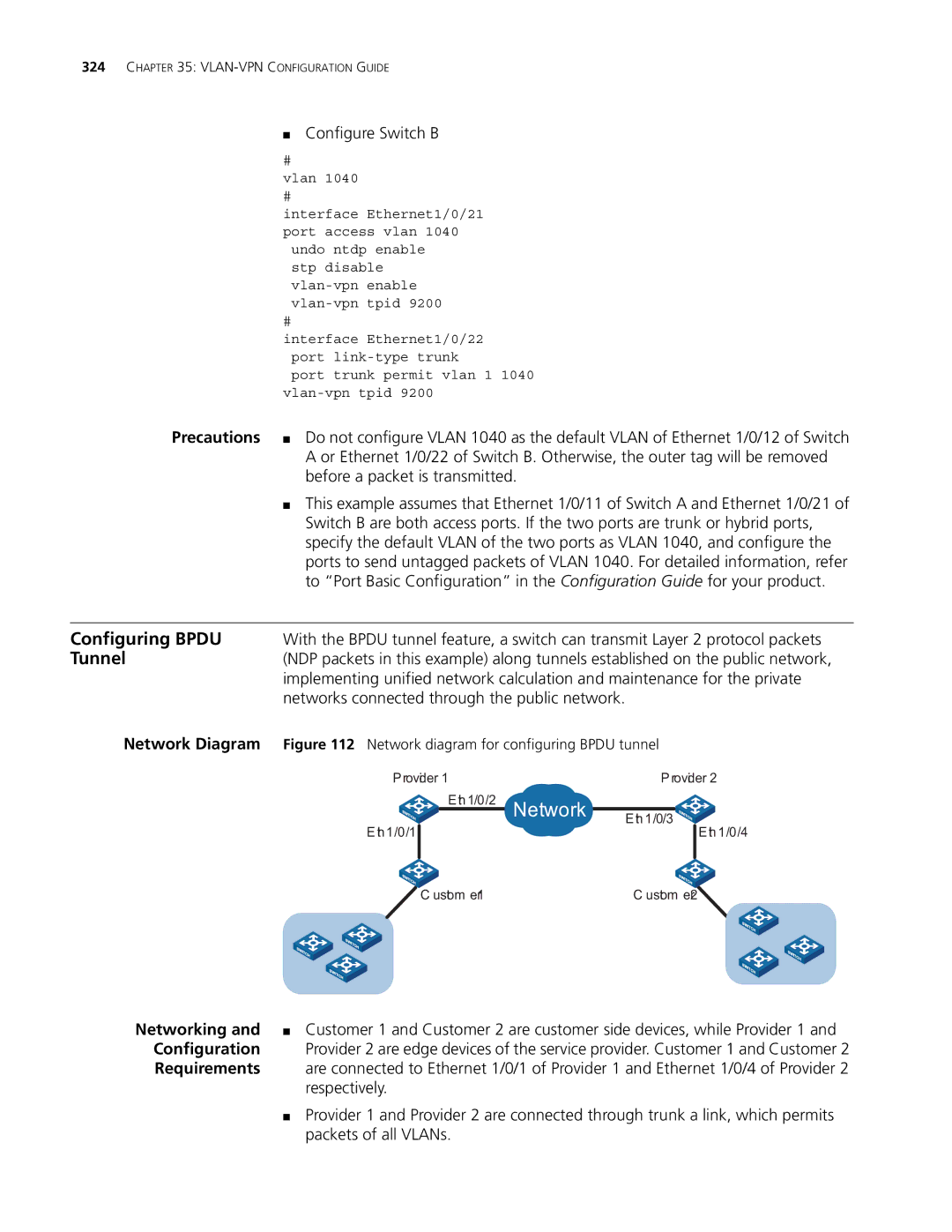
Network Diagram | Figure 112 Network diagram for configuring BPDU tunnel | ||||
| P rovider 1 |
| P rovider 2 | ||
|
| E th 1/0/2 | Network |
|
|
|
|
| E th 1/0/3 | ||
|
|
|
| ||
| E th 1/0/1 |
|
|
| E th 1/0/4 |
|
|
|
|
|
|
|
| C ustom er1 |
| C ustom er2 | |
Networking and | ■ Customer 1 and Customer 2 are customer side devices, while Provider 1 and |
Configuration | Provider 2 are edge devices of the service provider. Customer 1 and Customer 2 |
Requirements | are connected to Ethernet 1/0/1 of Provider 1 and Ethernet 1/0/4 of Provider 2 |
| respectively. |
| ■ Provider 1 and Provider 2 are connected through trunk a link, which permits |
| packets of all VLANs. |