POE/POE PROFILE CONFIGURATION
28 GUIDE
PoE Configuration | Power over Ethernet |
| |
| implement power supply and data transmission simultaneously. |
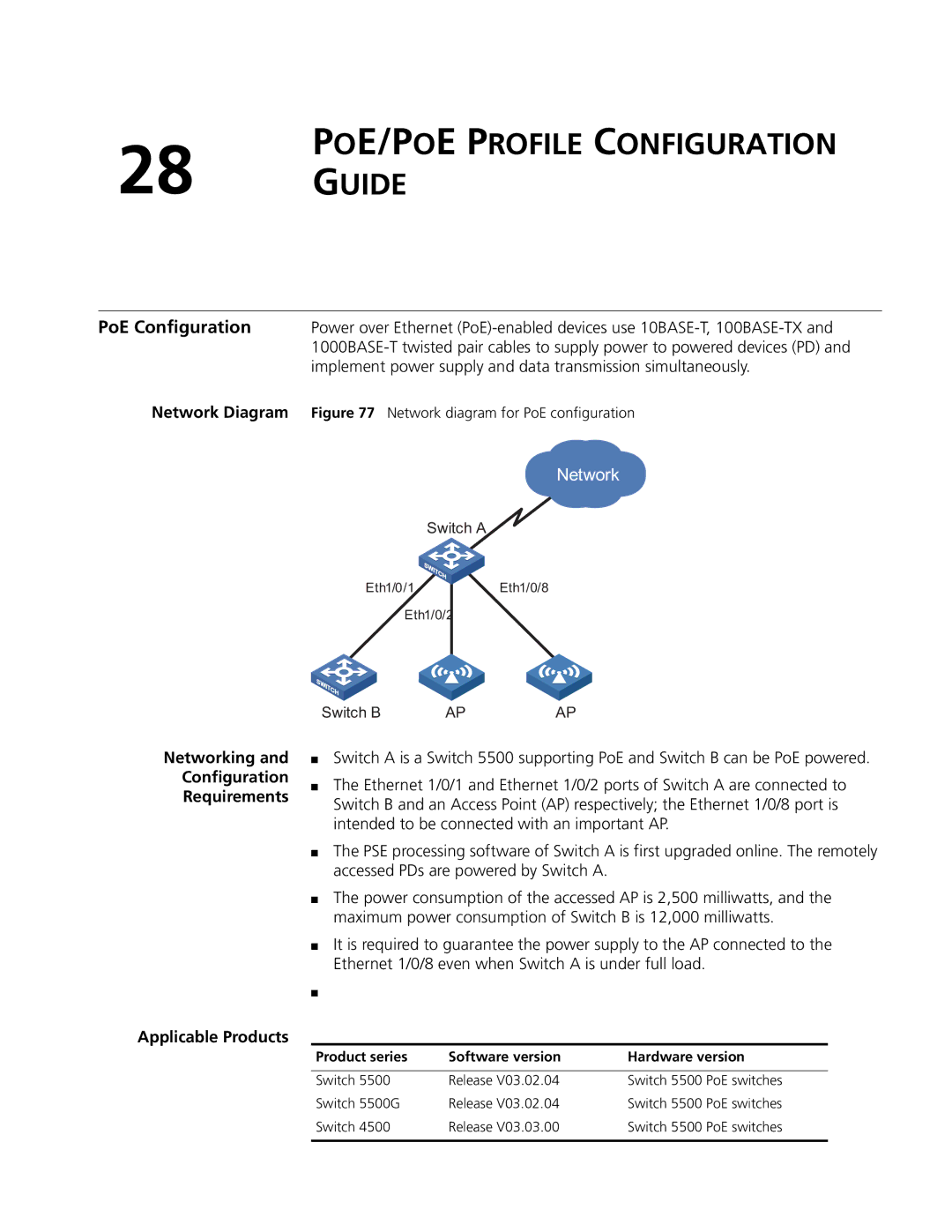
Network Diagram | Figure 77 Network diagram for PoE configuration |
Network
Switch A
Eth1/0/1Eth1/0/8
Eth1/0/2
Networking and
Configuration
Requirements
Switch B | AP | AP |
■Switch A is a Switch 5500 supporting PoE and Switch B can be PoE powered.
■The Ethernet 1/0/1 and Ethernet 1/0/2 ports of Switch A are connected to Switch B and an Access Point (AP) respectively; the Ethernet 1/0/8 port is intended to be connected with an important AP.
■The PSE processing software of Switch A is first upgraded online. The remotely accessed PDs are powered by Switch A.
■The power consumption of the accessed AP is 2,500 milliwatts, and the maximum power consumption of Switch B is 12,000 milliwatts.
■It is required to guarantee the power supply to the AP connected to the Ethernet 1/0/8 even when Switch A is under full load.
■
Applicable Products
Product series | Software version | Hardware version |
|
|
|
Switch 5500 | Release V03.02.04 | Switch 5500 PoE switches |
Switch 5500G | Release V03.02.04 | Switch 5500 PoE switches |
Switch 4500 | Release V03.03.00 | Switch 5500 PoE switches |
|
|
|