20
VRRP CONFIGURATION GUIDE
Single VRRP Group Virtual Router Redundancy Protocol (VRRP) is an
Configuration RFC 2338. In LANs with multicast or broadcast capabilities (such as Ethernet), VRRP can avoid single point failure through establishing backup links without modifying the configuration of dynamic routing protocols and router discovery protocols.
You can add two or more switches into a single VRRP group, which can provide two or more reliable links to the outside networks, therefore avoiding communication interruption resulting from single- or multi- point failure.
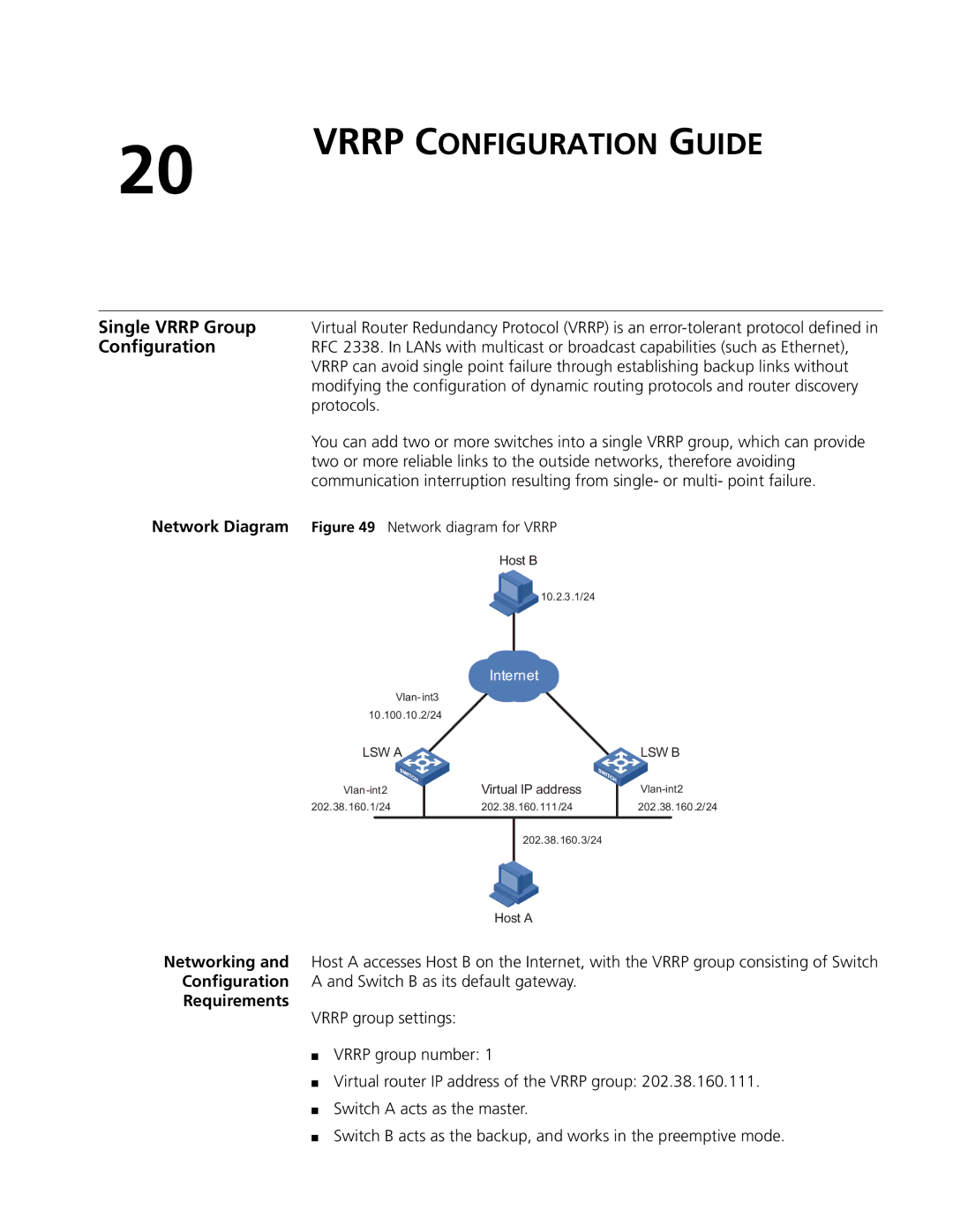
Network Diagram Figure 49 Network diagram for VRRP
Host B
![]()
![]() 10.2.3.1/24
10.2.3.1/24
|
|
| Internet |
|
|
| |
| Vlan- int3 |
|
|
|
|
| |
10.100.10.2/24 |
|
|
|
|
| ||
LSW A | Virtual IP address |
| LSW B | ||||
| |||||||
|
|
| |||||
|
| ||||||
202.38.160.1/24 |
| 202.38.160.111/24 |
| 202.38.160.2/24 | |||
|
|
|
|
|
|
| |
|
|
|
| 202.38.160.3/24 |
|
|
|
|
|
|
|
|
|
|
|
Host A
Networking and Host A accesses Host B on the Internet, with the VRRP group consisting of Switch Configuration A and Switch B as its default gateway.
Requirements
VRRP group settings:
■VRRP group number: 1
■Virtual router IP address of the VRRP group: 202.38.160.111.
■Switch A acts as the master.
■Switch B acts as the backup, and works in the preemptive mode.