220CHAPTER 23: QOS/QOS PROFILE CONFIGURATION GUIDE
■The Switch 4210 supports the WRR queue scheduling algorithm and the high
■The Switch 4210, 5500, and 5500G provide the default
Table 3
802.1p precedence (CoS) | Local precedence |
|
|
0 | 2 |
1 | 0 |
2 | 1 |
3 | 3 |
4 | 4 |
5 | 5 |
6 | 6 |
7 | 7 |
|
|
Configuring Traffic
Redirection and Traffic
Accounting
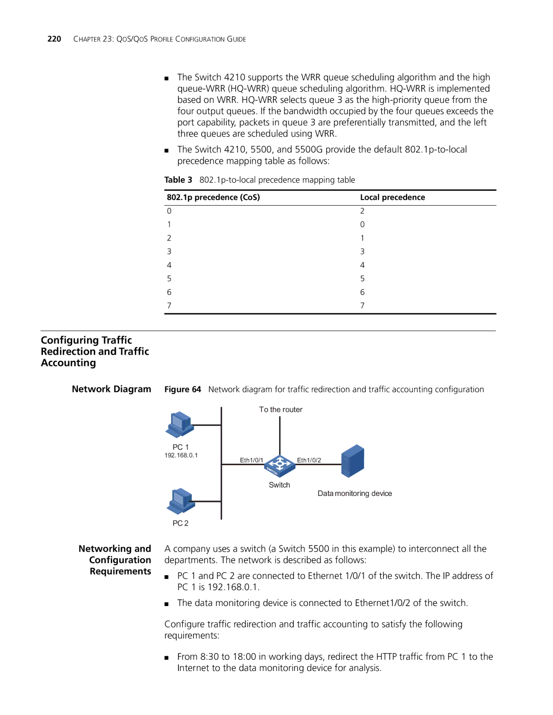
Network Diagram Figure 64 Network diagram for traffic redirection and traffic accounting configuration
PC 1
192.168.0.1
To the router
Eth1/0/1 |
| Eth1/0/2 |
|
|
|
Switch
Data monitoring device
PC 2
Networking and
Configuration
Requirements
A company uses a switch (a Switch 5500 in this example) to interconnect all the departments. The network is described as follows:
■PC 1 and PC 2 are connected to Ethernet 1/0/1 of the switch. The IP address of PC 1 is 192.168.0.1.
■The data monitoring device is connected to Ethernet1/0/2 of the switch.
Configure traffic redirection and traffic accounting to satisfy the following requirements:
■From 8:30 to 18:00 in working days, redirect the HTTP traffic from PC 1 to the Internet to the data monitoring device for analysis.