14
MSTP CONFIGURATION GUIDE
Configuring MSTP | The Switch 5500 supports the Multiple Spanning Tree Protocol (MSTP), which | |||
| allows you to map one or multiple VLANs to a multiple spanning tree instance | |||
| (MSTI). Note that one VLAN can be mapped to only one MSTI. With MSTP, the | |||
| packets of a specific VLAN are transmitted in the MSTI to which the VLAN is | |||
| mapped, thus saving overhead and reducing resource utilization. | |||
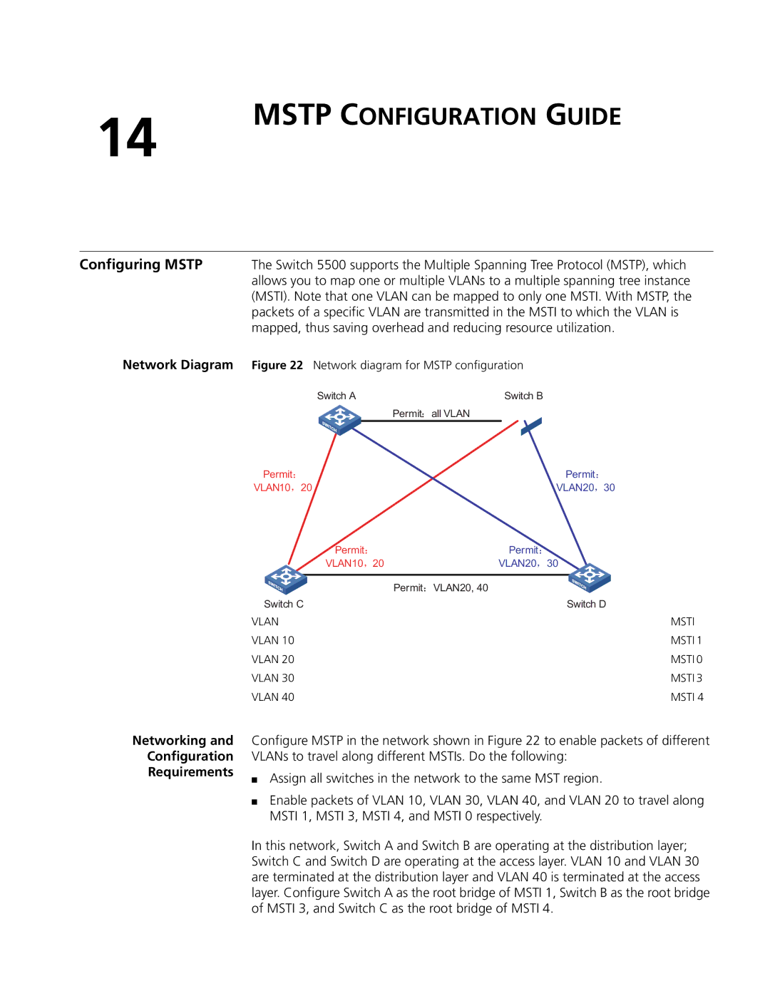
Network Diagram | Figure 22 Network diagram for MSTP configuration | |||
| Switch A |
| Switch B | |
|
| Permit | all VLAN |
|
Permit | Permit |
VLAN10 20 | VLAN20 30 |
| Permit | Permit | |
| VLAN10 20 | VLAN20 30 | |
|
|
|
|
| Permit | VLAN20, 40 | |
Switch C | Switch D | ||
VLAN |
| MSTI | |
VLAN 10 |
| MSTI 1 | |
VLAN 20 |
| MSTI 0 | |
VLAN 30 |
| MSTI 3 | |
VLAN 40 |
| MSTI 4 | |
Networking and
Configuration
Requirements
Configure MSTP in the network shown in Figure 22 to enable packets of different VLANs to travel along different MSTIs. Do the following:
■Assign all switches in the network to the same MST region.
■Enable packets of VLAN 10, VLAN 30, VLAN 40, and VLAN 20 to travel along MSTI 1, MSTI 3, MSTI 4, and MSTI 0 respectively.
In this network, Switch A and Switch B are operating at the distribution layer; Switch C and Switch D are operating at the access layer. VLAN 10 and VLAN 30 are terminated at the distribution layer and VLAN 40 is terminated at the access layer. Configure Switch A as the root bridge of MSTI 1, Switch B as the root bridge of MSTI 3, and Switch C as the root bridge of MSTI 4.