Configuring Access Management with Port Isolation 335
Configuring Access
Management with
Port Isolation
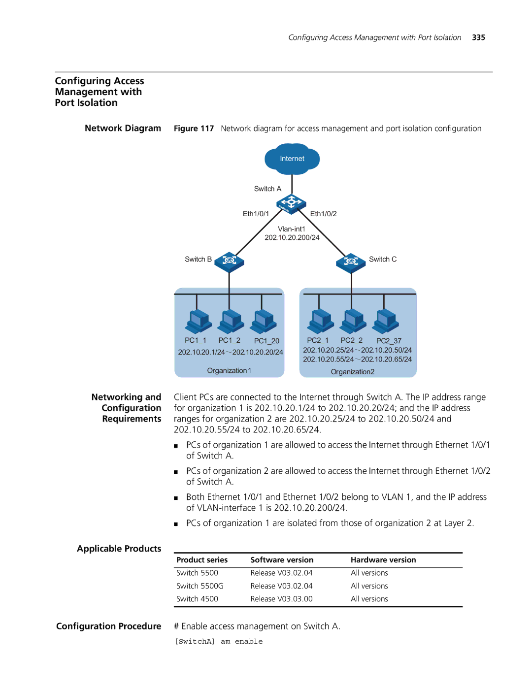
Network Diagram Figure 117 Network diagram for access management and port isolation configuration
Internet
Switch A
Eth1/0/1 ![]()
![]() Eth1/0/2
Eth1/0/2
202.10.20.200/24
Switch B |
|
|
| Switch C | ||||
|
|
|
|
|
|
|
|
|
|
|
|
|
|
|
|
|
|
|
|
|
|
|
|
|
|
|
PC1_1 PC1_2 | PC1_20 | PC2_1 PC2_2 | PC2_37 | ||
202.10.20.1/24 | 202.10.20.20/24 | 202.10.20.25/24 | 202.10.20.50/24 | ||
|
|
| 202.10.20.55/24 | 202.10.20.65/24 | |
Organization1 |
| Organization2 |
| ||
Networking and Client PCs are connected to the Internet through Switch A. The IP address range Configuration for organization 1 is 202.10.20.1/24 to 202.10.20.20/24; and the IP address Requirements ranges for organization 2 are 202.10.20.25/24 to 202.10.20.50/24 and
202.10.20.55/24 to 202.10.20.65/24.
■PCs of organization 1 are allowed to access the Internet through Ethernet 1/0/1 of Switch A.
■PCs of organization 2 are allowed to access the Internet through Ethernet 1/0/2 of Switch A.
■Both Ethernet 1/0/1 and Ethernet 1/0/2 belong to VLAN 1, and the IP address of
■PCs of organization 1 are isolated from those of organization 2 at Layer 2.
Applicable Products
Product series | Software version | Hardware version |
|
|
|
Switch 5500 | Release V03.02.04 | All versions |
Switch 5500G | Release V03.02.04 | All versions |
Switch 4500 | Release V03.03.00 | All versions |
|
|
|
Configuration Procedure # Enable access management on Switch A.
[SwitchA] am enable