27
CLUSTER CONFIGURATION GUIDE
Cluster Configuration The cluster function is implemented through 3Com Group Management Protocol version 2 (Switch Clusteringv2). Using Switch Clusteringv2, you can manage multiple switches through the public IP address of a master device. In a cluster, the master switch is called the management device, and the managed switches are called member devices. The member devices are not configured with public IP addresses. They are managed and maintained through the management device redirection.
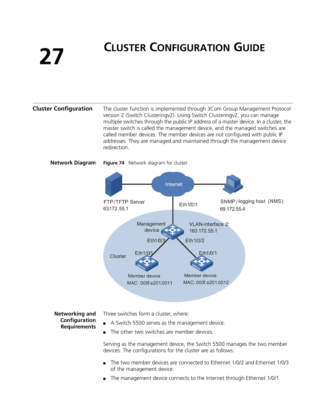
Network Diagram Figure 74 Network diagram for cluster
| Internet | SNMP / logging host (NMS) | ||
FTP/TFTP Server | Eth1/0/1 | |||
63.172.55.1 |
| 69.172.55.4 | ||
|
| |||
| Management | |||
| device | 163.172.55.1 |
| |
| Eth1/0/3 | Eth1/0/2 |
| |
Cluster | Eth1/0/1 | Eth1/0/1 |
| |
|
|
|
| |
| Member device | Member device |
| |
| MAC: 000f.e201.0011 | MAC: 000f.e201.0012 | ||
Networking and
Configuration
Requirements
Three switches form a cluster, where:
■A Switch 5500 serves as the management device.
■The other two switches are member devices.
Serving as the management device, the Switch 5500 manages the two member devices. The configurations for the cluster are as follows:
■The two member devices are connected to Ethernet 1/0/2 and Ethernet 1/0/3 of the management device.
■The management device connects to the Internet through Ethernet 1/0/1.